Home Blog Page 95

ControlLogix, CompactLogix – Can multiple controllers control the same Ethernet I/O? (P28)

In The Automation Podcast: Episode 28, we discuss if Multiple ControlLogix Controllers can Control the Same I/O.

Note – You’ll find more information about multiple controllers using the same I/O in our companion article below:

Listen to the Podcast:


Until next time, Peace ✌️ 

If you enjoy this episode please give it a Like, and consider Sharing as this is the best way for us to find new guests to come on the show.

Shawn M Tierney
Technology Enthusiast & Content Creator

Eliminate commercials and gain access to my weekly full length hands-on, news, and Q&A sessions by becoming a member at The Automation Blog or on YouTube. You'll also find all of my affordable PLC, HMI, and SCADA courses at TheAutomationSchool.com.

shawntierney avatar

PanelView 5000: What We Know So Far

The PanelView 5000 as shown at RSTechED 2012


The PanelView 5000 as shown at RSTechED 2012The PanelView 5000 was first previewed at Rockwell’s Automation Fair 2011, but not much was being said about it at the time.

In fact so little was being said, they wouldn’t even tell us the name of the software package which programmed it.

From Automation Fair 2011 to RSTechED 2012

Fast forward several months to RSTechED 2012, and I was one of the lucky souls to get a seat in the hands-on session with this new Allen-Bradley HMI.

It’s been a couple of years since that session, but at the time the software seemed very stable, and I figured it would be released in mere months.

Oh, and about the software… it was integrated into what we now know as Studio 5000.

Today when most people here of Studio 5000 they think it’s just version 21 of RSLogix 5000. But that’s only the “Logix Designer.” As we found out in the hands-on lab mentioned above, Studio 5000 will someday come with a “View Designer” which is what programs the PanelView 5000.

The PanelView 5000 as shown at RSTechED 2012In 2012 we were told all “in support” owners of Studio 5000 would get View Designer free when it was released along side a new version of Logix designer. I was like “very cool.” Yeah, that was until I noticed the price of Studio 500 has climbed drastically over the years. I guess nothing is ever free.

Back to the lab for a moment: One of the things that really impressed me was the replacement for the RSView/FTView animation system from 1995. The new View Designer system demonstrated in the lab lets you bind a tag to almost any property of any object. Think height, width, color, etc all bindable to the tag of your choice. Pretty cool stuff.

Beyond Automation Fair 2012

Shown again at Automation Fair 2012, the PanelView 5000 was really taking shape. The product line was slated to come out in two versions. The 5300 would be the standard version housed in plastic, and aimed at the OEM market.

The 5500 was to be the enhanced version. It was housed in metal, had more powerful electronics, and was aimed at high end applications.

At the time, rumor had the PanelView 5000 releasing the following year (2013.) As clients started repeating this rumor, I downplayed that timeframe stating it was so far in the future we really couldn’t predict when the product would actually launch.

Unfortunately, my comments were truer that I thought.  Two RSTechED’s and one Automation Fair later, and there’s been no public signs or sightings of the PanelView 5000.

While I’m confident it’s still in development, I think the very early previewing of the product combined with subsequent delays have put us in a position where we won’t hear about it again publically until it’s nearly shipping.

So, have you heard anything about the PV5000? If you have, I’d loved to here what – just fill out the “post a comment or question” link below to share what you know.

Until next time, Peace ✌️ 

If you enjoy this episode please give it a Like, and consider Sharing as this is the best way for us to find new guests to come on the show.

Shawn M Tierney
Technology Enthusiast & Content Creator

Eliminate commercials and gain access to my weekly full length hands-on, news, and Q&A sessions by becoming a member at The Automation Blog or on YouTube. You'll also find all of my affordable PLC, HMI, and SCADA courses at TheAutomationSchool.com.

shawntierney avatar

PanelView 800 – What we know so far (2014)

PVc-Questions


PVc-QuestionsI’m a long time user and fan of Rockwell’s HMI’s, going all the way back to the original PanelView (1200) and beyond.

So whenever I hear that a new Allen-Bradley PanelView is coming, I can’t help but want to know more.

In the case of the PanelView 800, while I’ve heard some rumors it was in development, it wasn’t until last week that I found anything mentioned about it publically.

The PanelView 800: Coming to Automation Fair 2014

The rumors I heard also mentioned the product would be introduced at AF2014, and would begin shipping shortly there after.

So when I noticed the Automation Fair Pre-Show Program was out, I searched though it for any news. What I found is, Rockwell is indeed showcasing the PV800 at this year’s Automation Fair.

Beyond the show flow, the PanelView 800 will also be showcased in a sixty minute in-depth technical presentation (session T29)

What we know so far:

Based on the description of that session, the following is what we know so far.

  • The new PanelViewTM 800 HMI is being designed and marketed for use with the Micro800 and MicroLogix family of Allen-Bradley programmable controllers.
  • The PanelViewTM 800 is also said to offer improved CPU performance with a faster boot time and improved responsiveness. But improved over what is not stated. If I had to guess, I would say the comparison is being made to the PanelView Component, as that product seems to be the most likely one replaced with a new low cost A-B HMI.
  • PVc-10-6-4-QuestionsThe PV800 comes in three screen sizes: 4″, 7″ and 10″
  • It also has better screen resolution. Again, I’m assuming it’s better resolution over a similarly sized PanelView Component model.
  • It programs with the same software as the PanelView Component HMI, Connected Components Workbench. This seems to imply it also shares the same editor as the PVc family, but that detail is not specified. Also not mentioned is which version of CCW will be compatible with the PV800. Possibly a new version, mabe v7?
  •  Lastly, the guide also mentions enhanced features of the PV800. These include a portrait mode, enhanced recipe feature, and improved symbol library.

Well, that’s all we know right now about the Allen-Bradley PanelView 800. If you would like to read the Automation Fair 2014 Pre-Show guide where I found this information, you can find it at http://www.AutomationFair.com.

Until next time, Peace ✌️ 

If you enjoy this episode please give it a Like, and consider Sharing as this is the best way for us to find new guests to come on the show.

Shawn M Tierney
Technology Enthusiast & Content Creator

Eliminate commercials and gain access to my weekly full length hands-on, news, and Q&A sessions by becoming a member at The Automation Blog or on YouTube. You'll also find all of my affordable PLC, HMI, and SCADA courses at TheAutomationSchool.com.

shawntierney avatar

MicroLogix 1400 Expansion I/O

MicroLogix-1400-Expansion-IO-Fi


MicroLogix-1400-Expansion-IO-PortThe MicroLogix 1400’s base I/O can be expanded using 1762  I/O modules. In this article we’ll describe the details of how this is accomplished.

The right front of the MicroLogix 1400 has a small cover over top of a 1762 I/0 expansion port, and the first step in adding 1762 I/O to a MicroLogix 1400 is to power down the unit, and remove the cover.

Next, you’ll find that your 1762 expansion I/O modules come with a ribbon cable and connector on the left side. Also on the front right of the expansion module you’ll find another small cover over the top of an additional expansion I/O port.

MicroLogix-1400-Expansion-IO-1762-IO-ConnectorTo install your 1762 expansion module, simply plug the ribbon cable connector into the MicroLogix 1400’s expansion I/O connector and replace the cover. Then, to connect additional 1762 expansion I/O modules, remove the expansion cover from the first module and plug the second module into it, replacing the cover when done.

Repeat this process until you have installed all your 1762 expansion modules, or have reached the power limit of the MicroLogix 1400’s expansion bus.

MicroLogix-1400-Expansion-IO-with-Expansion-IOTo simplify the selection of expansion modules, Rockwell designed the MicroLogix 1400 to accept up to any seven 1762 I/O modules. This is three more than the MicroLogix 1100, and different from the MicroLogix 1200 which supports 3 and 6 modules based on their current draw.

Well, that’s it for today’s article about MicroLogix 1400 expansion I/O. For more information on the installation of MicroLogix 1400 expansion I/O, see the manufacturer’s installation instructions HERE.

MicroLogix-1400-Expansion-IO-with-Expansion-IO-2And if you’ve have any comments, questions, or corrections, please feel free to fill out the “post a comment or question” for at the bottom of the page.

Until next time, Peace ✌️ 

If you enjoy this episode please give it a Like, and consider Sharing as this is the best way for us to find new guests to come on the show.

Shawn M Tierney
Technology Enthusiast & Content Creator

Eliminate commercials and gain access to my weekly full length hands-on, news, and Q&A sessions by becoming a member at The Automation Blog or on YouTube. You'll also find all of my affordable PLC, HMI, and SCADA courses at TheAutomationSchool.com.

shawntierney avatar

ControlLogix, CompactLogix – Data Logging Options (P27)

In The Automation Podcast: Episode 27, we discuss data logging options for Compact and ControlLogix

Note – You’ll find more information about data logging options for Compact and ControlLogix in our companion article below:

Listen to the Podcast:


Until next time, Peace ✌️ 

If you enjoy this episode please give it a Like, and consider Sharing as this is the best way for us to find new guests to come on the show.

Shawn M Tierney
Technology Enthusiast & Content Creator

Eliminate commercials and gain access to my weekly full length hands-on, news, and Q&A sessions by becoming a member at The Automation Blog or on YouTube. You'll also find all of my affordable PLC, HMI, and SCADA courses at TheAutomationSchool.com.

shawntierney avatar

MicroLogix 1400 Installation and Mounting

MicroLogix-1400-Front-Top-Fi


MicroLogix-1400-Front-TopThe MicroLogix 1400 has an extensive installation document referred to as “installation instructions” which you can obtain electronically from Rockwell’s website HERE.

While these “installation instructions” cover many different topics, in this blog article I’ll be focusing on the installation and mounting of the controller itself.

MIcroLogix-1400-BottomTo allow for installation in the widest temperature range possible, the MicroLogix 1400 programmable controller is vented on the top, bottom, and left side. This venting is for convection cooling of the internal circuits of the controller. In order to allow sufficient air to flow through the vents, you need to allow for two inches (50mm) of spacing on the three vented sides.

MicroLogix-1400-LeftThe MicroLogix 1400 should only be mounted horizontally. And it’s very important not to allow any debris to fall inside the unit’s vents. Metal filings or wire strands which fall into the MicroLogix can damage or destroy it’s internal circuits.

To aid in avoiding such occurrences, the MicroLogix 1400 comes equipped with a protective debris strip installed on the top of the unit. This strip should not be MicroLogix-1400-Topremoved until after all panel wiring and drilling above where the unit will be mounted is complete, and the MicroLogix 1400 itself is installed and wired.

The MicroLogix 1400 should also not be powered on while the protective strip is installed. If this caution is not followed, the controller’s circuits could overheat and become permanently damaged.

MicroLogix-1400-BackWhile most installations will find the MicroLogix 1400 mounted to a din rail, four mountings holes are also provided for surface mounting. When used, they are typically utilized to mount the Micro to the backpanel of an electrical enclosure using #8 or M4 screws.

To aid in surface mounting installations, the product’s, “Installation Instructions,” includes a “mounting template” foldout on the last page to aid in spacing mounting holes accurately.

Well, that’s in for today’s article reviewing the installation and mounting of a MicroLogix 1400 programmable controller. For more information about installing the MicroLogix 1400, you can find the complete manufacturer’s installation instructions HERE.

And if you’ve have any comments, questions, or corrections, please feel free to fill out the “post a comment or question” for at the bottom of the page.

Until next time, Peace ✌️ 

If you enjoy this episode please give it a Like, and consider Sharing as this is the best way for us to find new guests to come on the show.

Shawn M Tierney
Technology Enthusiast & Content Creator

Eliminate commercials and gain access to my weekly full length hands-on, news, and Q&A sessions by becoming a member at The Automation Blog or on YouTube. You'll also find all of my affordable PLC, HMI, and SCADA courses at TheAutomationSchool.com.

shawntierney avatar

MicroLogix 1100 (M36)


In The Automation Minute: Episode 36, I introduce you to the Allen-Bradley MicroLogix 1100 Programmable Controller

Note: To find out how you can get a copy of my complete Micro Programmable Controller training video, please visit http://www.TheAutomationSchool.com


Check out our Video Collection #1 here, which includes the first five seasons of our shows (over 280 episodes and 29 hours!) for just $30!

Until next time, Peace ✌️ 

If you enjoy this episode please give it a Like, and consider Sharing as this is the best way for us to find new guests to come on the show.

Shawn M Tierney
Technology Enthusiast & Content Creator

Eliminate commercials and gain access to my weekly full length hands-on, news, and Q&A sessions by becoming a member at The Automation Blog or on YouTube. You'll also find all of my affordable PLC, HMI, and SCADA courses at TheAutomationSchool.com.

shawntierney avatar

The Allen-Bradley MicroLogix 1400

MicroLogix-1400-Front-Fi


MicroLogix-1400-FrontIn 2008, forteen years after the original MicroLogix 1000 was released, and three years after the MicroLogix 1100, Rockwell introduced the MicroLogix 1400.

This new micro PLC built on the success of the MicroLogix 1100, expanding on the built-in I/O count as well as the number of expansion modules supported.

Featuring 32 digital I/O, 6 optional analog I/O, and support for any seven 1762 expansion modules, the MicroLogix 1400 supported more total I/O than any previous model (up to 256 digital I/O points.)

MicroLogix-1400-Front-BottomAs with the MicroLogix 1000, 1200, and 1100, the MicroLogix 1400’s DC input models supported either sinking or sourcing inputs. And like the MicroLogix 1200, the MicroLogix 1400 also came equipped with removable terminal blocks and wiring labels. If fact, the 1400 uses the same RTB’s as the MicroLogix 1200 40-point models.

The DC input models also supported six high speed inputs which all could be used as 100KHz high speed counters. The DC output models also included three high speed outputs which could be used for 100KHz PTOs, or 40KHz PWM outputs.

The MicroLogix 1400 was similar to the 1100 in the fact that it came with the same 8 pin Mini-Din serial port (COMM 0) that supported both RS-232 MicroLogix-1400-Front-Openand RS-485. This port supported DF1 Full Duplex, DF1 Half Duplex Master or Slave, DF1 Radio Modem, ASCII, DH-485, Modbus RTU Master or Slave, as well as DNP3 Slave.

However, the 1400 also included a second serial port (COMM 2.) This additional port was a DB9 RS232C port that supported DF1, DH485, Modbus RTU, DNP3, and ASCII protocols.

MicroLogix-1400-BottomThe MicroLogix 1400 also came with an RJ45 10/100 Ethernet port as did the 1100. This port initially supported Ethernet/IP Peer to Peer messaging (not implicit I/O connections,) as well as Boot-P, DHCP, Web Server and Email functions.

In 2010, Rockwell released the series B model which enhanced the Ethernet port adding Modbus TCP and DNP3 over IP. It also added the ability to disable incoming connecting, duplicate IP detection, and unconnected messaging.

Being released three years after the 1100 allowed the 1400 to come with all the features of the 1100, as well as many enhancements. Beyond the expanded I/O, high speed DC I/O, and other features mentioned above, the MicroLogix 1400 also had the following improvements over the 1100:

  • MicroLogix-1400-LCDMore than double the memory (20K versus 8K)
  • Double the program execution speed (.7ms vs 1.5ms per 1K)
  • Trigonometry instruction support
  • Advanced math instructions (XY, CPT)
  • Advanced timing instructions (Read High-speed Clock, Compute Time Diff)
  • Backlit LCD
  • IP Address settable from LCD
  • Data Table accessible form LCD

Just like the 1100, the 1400’s embedded LCD display replaced many of the standard LED indicators found on other MicroLogix models. It was used to display the status of I/O points, as well as change the controllers “mode.” It was also used enable the DCOMM setting for channel 0, and to display controller settings like the Ethernet address. It even supported displaying of user defined messages using an “LCD” instruction.

RSLOGIX-MICROThe MicroLogix 1400 was also like the 1100 in the fact that it included an additional 128K memory chip which could be used with the DLG instruction for datalogging. 64K of that same memory could also be used with an RCP recipe instruction.

The MicroLogix 1400 was also programmed with the same Windows based RSLogix 500 software (version 8.1 or greater) that programmed the SLC-500 and other MicroLogix processors, as well as the MicroLogix only programming software, RSLogix Micro Starter ($129.)

Today, with it’s advanced features and many enhancements over the MicroLogix 1100, the MicroLogix 1400 is the pinnacle of Rockwell’s popular MicroLogix programmable controller family.

If you would like to find out more about the MicroLogix 1400 you can visit the manufacturer’s product webpage HERE.

Until next time, Peace ✌️ 

If you enjoy this episode please give it a Like, and consider Sharing as this is the best way for us to find new guests to come on the show.

Shawn M Tierney
Technology Enthusiast & Content Creator

Eliminate commercials and gain access to my weekly full length hands-on, news, and Q&A sessions by becoming a member at The Automation Blog or on YouTube. You'll also find all of my affordable PLC, HMI, and SCADA courses at TheAutomationSchool.com.

shawntierney avatar

Flashback Friday! RSView32 Star Trek Menu’s Demo

RSView32_Star_Trek_Menus_FF


RSView32_Star_Trek_Menus_FFWelcome to The Automation Blog’s “Flashback Friday!”

Today I’m highlighting an RSView32 project I wrote to make RSView32 look like the Star Trek LCARS computer system.

In 2001 an engineer told me the story about how one of his clients wanted him to create a SCADA project with menu’s that looked like the computer system out of Star Trek The Next Generation.

Intrigued with the idea, I attempted the project myself and this demo is the result.

To read the original story and download the project, see the reposted article HERE on The Automation Blog:

And if you have any questions, comments, or suggestions please don’t hesitate to share them with us by using the “post a comment or question” link below.

Until next time, Peace ✌️ 

If you enjoy this episode please give it a Like, and consider Sharing as this is the best way for us to find new guests to come on the show.

Shawn M Tierney
Technology Enthusiast & Content Creator

Eliminate commercials and gain access to my weekly full length hands-on, news, and Q&A sessions by becoming a member at The Automation Blog or on YouTube. You'll also find all of my affordable PLC, HMI, and SCADA courses at TheAutomationSchool.com.

shawntierney avatar

Beginner’s PLC (P26)

In The Automation Podcast: Episode 26, we discuss two different options when choosing a Beginner’s PLC.

Note – You’ll find more information about choosing a Beginner’s PLC in our companion article below:

Listen to the Podcast:

NOTE – Below are the links to products mentioned in this podcast:


Until next time, Peace ✌️ 

If you enjoy this episode please give it a Like, and consider Sharing as this is the best way for us to find new guests to come on the show.

Shawn M Tierney
Technology Enthusiast & Content Creator

Eliminate commercials and gain access to my weekly full length hands-on, news, and Q&A sessions by becoming a member at The Automation Blog or on YouTube. You'll also find all of my affordable PLC, HMI, and SCADA courses at TheAutomationSchool.com.

shawntierney avatar

Finding a MicroLogix 1100’s IP and MAC Address

MicroLogix-1100-MAC-IP-Fi


The MicroLogix 1100 includes an Ethernet port with a fixed MAC address, as well as a settable Ethernet IP address. In today’s article we’ll show you how to find both.

Finding the MAC address on a MicroLogix 1100:

1) Thankfully, each MicroLogix 1100 comes with it’s unique MAC address stenciled on it. To find it, remove the battery compartment cover on the right side of the Micro:

MicroLogix-1100-MAC-IP-Location2) At the very bottom of the compartment, directly under the battery plug, you will see the MicroLogix 1100 MAC address. . The MAC Address of the unit pictured below is: 00:0F:73:00:23:26
MicroLogix-1100-MAC

Finding the IP and MAC address of a MicroLogix 1100 using the built-in LCD:

1) When the MicroLogix 1100 is powered on, it displays the I/O Status screen as shown below:

MicroLogix-1100-LCD-Home-IO-Status2) To find the Micro’s IP and MAC address using the LCD,  we need to access it’s menu. To do this, press the ESC button and you should see the display below:

MicroLogix-1100-LCD-Menu3) Next, press the down arrow button four times to select “Advanced Set,” then press the OK button:

MicroLogix-1100-LCD-Menu-Page-2-User-Display-Selected4) Here, press the down arrow button twice to select “ENET CFG,” then press the OK button:

MicroLogix-1100-LCD-Advanced-Menu-ENET-Selected5) Now you will see displayed the MAC address followed by the IP address of your MicroLogix 1100.

MicroLogix-1100-LCD-Mac-Ip-Display6) To return to the I/O Status display, press the ESC button until you see the main menu, and then select “I/O Status” and press the OK button:

MicroLogix-1100-LCD-MenuI hope the above procedure on how to find a MicroLogix 1100’s IP and MAC address was helpful.

If you have any comments, questions, suggestions, or corrections, please feel free to leave them with us by filling out the “post a comment or question” link below.

Until next time, Peace ✌️ 

If you enjoy this episode please give it a Like, and consider Sharing as this is the best way for us to find new guests to come on the show.

Shawn M Tierney
Technology Enthusiast & Content Creator

Eliminate commercials and gain access to my weekly full length hands-on, news, and Q&A sessions by becoming a member at The Automation Blog or on YouTube. You'll also find all of my affordable PLC, HMI, and SCADA courses at TheAutomationSchool.com.

shawntierney avatar

View Studio – Logix Tag Browsing (Flashback Video 10)


In The Automation Minute, Flashback Episode 10, Shawn Tierney walks you through Rockwell’s FactoryTalk View Studio Logix Tag Browsing.

Note: To find out how you can get a copy of our complete PanelView Plus and View Studio Training video visit http://www.TheAutomationSchool.com


Check out our Video Collection #1 here, which includes the first five seasons of our shows (over 280 episodes and 29 hours!) for just $30!

Until next time, Peace ✌️ 

If you enjoy this episode please give it a Like, and consider Sharing as this is the best way for us to find new guests to come on the show.

Shawn M Tierney
Technology Enthusiast & Content Creator

Eliminate commercials and gain access to my weekly full length hands-on, news, and Q&A sessions by becoming a member at The Automation Blog or on YouTube. You'll also find all of my affordable PLC, HMI, and SCADA courses at TheAutomationSchool.com.

shawntierney avatar

Using the MicroLogix 1100’s LCD To Change Trim Pot Values

MicroLogix-1100-LCD-TrimPot-Fi


The MicroLogix 1100’s LCD display allows access to many of it’s features and functions.

In today’s article, we show you how to use it to change Trim Pot values:

Changing Trim Pot values on the MicroLogix 1100

1) When the MicroLogix 1100 is powered on, it displays the I/O Status screen as shown below:

MicroLogix-1100-LCD-Home-IO-Status2) To change the Micro’s Trim Pot values, we need to access the LCD menu. To do this, press the ESC button and you should see the display below:

MicroLogix-1100-LCD-Menu3) Next, press the down arrow button four times to select “Advanced Set,” then press the OK button:

MicroLogix-1100-LCD-Menu-Page-2-User-Display-Selected

4) Here, press the down arrow button three times to select “TrimPot Set,” then press the OK button:

MicroLogix-1100-LCD-TrimPot-Menu5) Now select either “LCD:0.POT0” or “LCD:0.POT1,” and press the OK button.

MicroLogix-1100-LCD-TrimPot-Menu-26) Here you see the Trim Pot Min and Max values (TMIN and TMAX) as well as the value for POT0 (or POT1) flashing:

MicroLogix-1100-LCD-TrimPot-Display7) Use the Left and Right arrow buttons to select a POT digit, then use the Up and Down arrow buttons to change the selected digit’s value.

MicroLogix-1100-LCD-TrimPot-Change8) When done, to return to the I/O Status display press the ESC button until you see the main menu. Then select “I/O Status” and press the OK button:

MicroLogix-1100-LCD-MenuI hope the above procedure on how to use the MicroLogix 1100’s LCD display to change it’s Trim Pot values was helpful.

If you have any comments, questions, suggestions, or corrections, please feel free to leave them with us by filling out the “post a comment or question” link below.

Until next time, Peace ✌️ 

If you enjoy this episode please give it a Like, and consider Sharing as this is the best way for us to find new guests to come on the show.

Shawn M Tierney
Technology Enthusiast & Content Creator

Eliminate commercials and gain access to my weekly full length hands-on, news, and Q&A sessions by becoming a member at The Automation Blog or on YouTube. You'll also find all of my affordable PLC, HMI, and SCADA courses at TheAutomationSchool.com.

shawntierney avatar

Flashback Friday! RSView32 Simple Message Display Demo

RSView32_Simple_Message_Display_FF


RSView32_Simple_Message_Display_FFWelcome to The Automation Blog’s “Flashback Friday!”

Today I’m highlighting an RSView32 project I wrote demonstrating how to use a Combo Box as a Message Display.

In 2001 many former PanelView customers were beginning to use RSView32. And they would call frustrated they could not find a built-in Multistate Indicator like the one found in PanelBuilder32.

In response, I created this simple project to show how to use a Combo Box as a Simple Message Display.

To read the original story and download the project, see the reposted article HERE on The Automation Blog:

And if you have any questions, comments, or suggestions please don’t hesitate to share them with us by using the “post a comment or question” link below.

Until next time, Peace ✌️ 

If you enjoy this episode please give it a Like, and consider Sharing as this is the best way for us to find new guests to come on the show.

Shawn M Tierney
Technology Enthusiast & Content Creator

Eliminate commercials and gain access to my weekly full length hands-on, news, and Q&A sessions by becoming a member at The Automation Blog or on YouTube. You'll also find all of my affordable PLC, HMI, and SCADA courses at TheAutomationSchool.com.

shawntierney avatar

Using the MicroLogix 1100’s LCD To Enable Default Comms

MicroLogix-1100-LCD-DCOMM-Fi


The MicroLogix 1100’s LCD display allows access to many of it’s features and functions.

In today’s article, we show you how to use it to enable default comms:

NOTE: When “Default Comms” is enabled, the MicroLogix 1100’s Channel 0 serial port is toggled back to the factory default settings. These settings include the DF1 Full Duplex protocol, a baud rate of 19.2K, and CRC error checking. When “Default Comms” is disabled, Channel 0 returns to the currently loaded program’s settings.

Enabling Default Comms on the MicroLogix 1100

1) When the MicroLogix 1100 is powered on, it displays the I/O Status screen as shown below:

MicroLogix-1100-LCD-Home-IO-Status2) To enable “Default Comms,” we need to access the LCD menu. To do this, press the ESC button and you should see the display below:

MicroLogix-1100-LCD-Menu3) Next, press the down arrow button four times to select “Advanced Set,” then press the OK button:

MicroLogix-1100-LCD-Menu-Page-2-User-Display-Selected

4) Here, press the down arrow button once to select “DCOMM CFG,” then press the OK button:

MicroLogix-1100-LCD-Advanced-Menu-DCOMM-Selected5) Now press the up arrow button once to select “Enable,” and press the OK button.

MicroLogix-1100-LCD-DCOMM-Menu-Enable-Selected6) You should now see the message, “Comms config set to DF1 default.” You should also see the DCOMM indicator displayed near the top left of the LCD.

MicroLogix-1100-LCD-DCOMM-Menu-Enable-Message7) To return to the I/O Status display, press the ESC button until you see the main menu, and then select “I/O Status” and press the OK button:

MicroLogix-1100-LCD-MenuI hope the above procedure on how to use the MicroLogix 1100’s LCD display to enable “Default Comms” was helpful.

If you have any comments, questions, suggestions, or corrections, please feel free to leave them with us by filling out the “post a comment or question” link below.

Until next time, Peace ✌️ 

If you enjoy this episode please give it a Like, and consider Sharing as this is the best way for us to find new guests to come on the show.

Shawn M Tierney
Technology Enthusiast & Content Creator

Eliminate commercials and gain access to my weekly full length hands-on, news, and Q&A sessions by becoming a member at The Automation Blog or on YouTube. You'll also find all of my affordable PLC, HMI, and SCADA courses at TheAutomationSchool.com.

shawntierney avatar

View Studio – HMI Tag Browsing (Flashback Video 9)


In The Automation Minute, Flashback Episode 9, Shawn Tierney walks you through Rockwell’s FactoryTalk View Studio HMI Tag Browsing.

Note: To find out how you can get a copy of our complete PanelView Plus and View Studio Training video visit http://www.TheAutomationSchool.com


Check out our Video Collection #1 here, which includes the first five seasons of our shows (over 280 episodes and 29 hours!) for just $30!

Until next time, Peace ✌️ 

If you enjoy this episode please give it a Like, and consider Sharing as this is the best way for us to find new guests to come on the show.

Shawn M Tierney
Technology Enthusiast & Content Creator

Eliminate commercials and gain access to my weekly full length hands-on, news, and Q&A sessions by becoming a member at The Automation Blog or on YouTube. You'll also find all of my affordable PLC, HMI, and SCADA courses at TheAutomationSchool.com.

shawntierney avatar

Using the MicroLogix 1100’s LCD To Change Modes

MicroLogix-1100-LCD-Mode-Switch-Fi


The MicroLogix 1100’s LCD display allows access to many of it’s features and functions. In today’s article we show you how to use it to change this PLC’s mode:

Changing the MicroLogix 1100’s mode

1) When the MicroLogix 1100 is powered on, it powers up displaying I/O Status seen below:

MicroLogix-1100-LCD-Home-IO-StatusIn the above picture you can see this PLC is in the “remote run” mode since the RUN LED to the left of the LCD is on, and on the top right of the LCD Display you can see the word “REMOTE.”

2) To change this Micro’s “mode” we first need to access the LCD menu. To do this, press the ESC button and the menu below will be displayed:

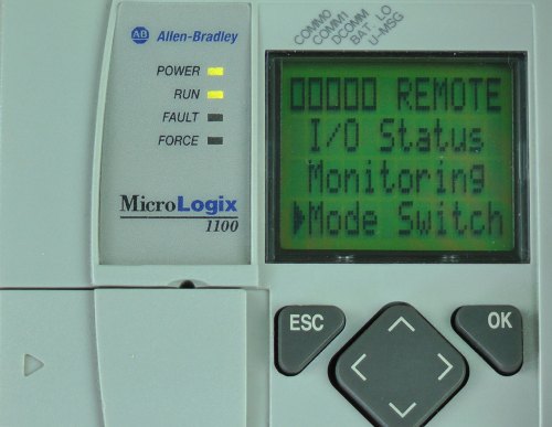
MicroLogix-1100-LCD-Menu3) Now press the down arrow button twice to select “Mode Switch,” and press the OK button:

MicroLogix-1100-LCD-Menu-Mode-Switch-Sel

4) Here, select the “mode” you would like to change MicroLogix 1100 to. We will choose “Program” in this example. Next press the OK button:

MicroLogix-1100-LCD-Mode-Switch-Menu-Program-Selected-in-Remote
5) Now you can see the RUN LED indicator to the left of the LCD is off. And the text in the top right of the LCD has changed to “PROG.” This indicates we have successfully change our MicroLogix 1100’s mode from “remote run” to “program” using its LCD display:

MicroLogix-1100-LCD-Mode-Switch-Menu-Program Selected-in-Program6) To return to the I/O Status display, press the ESC button until you see the main menu, and then select I/O Status and press the OK button:

MicroLogix-1100-LCD-Menu


I hope the above procedure on how to use the MicroLogix 1100’s LCD display to change it’s mode was helpful.

If you have any comments, questions, suggestions, or corrections, please feel free to leave them with us by filling out the “post a comment or question” link below.

Until next time, Peace ✌️ 

If you enjoy this episode please give it a Like, and consider Sharing as this is the best way for us to find new guests to come on the show.

Shawn M Tierney
Technology Enthusiast & Content Creator

Eliminate commercials and gain access to my weekly full length hands-on, news, and Q&A sessions by becoming a member at The Automation Blog or on YouTube. You'll also find all of my affordable PLC, HMI, and SCADA courses at TheAutomationSchool.com.

shawntierney avatar

MicroLogix 1100 Expansion I/O

MicroLogix-1100-Expansion-IO-Installed-Fi


MicroLogix-1100-Expansion-IO-PortThe MicroLogix 1100’s base I/O can be expanded using 1762 I/O modules. In this article we’ll describe the details of how this is accomplished.

On the right side of the front of a MicroLogix 1100 you’ll find a removable plastic cover covering the battery compartment as well as the 1762 I/O expansion port. The first step in adding 1762 I/O to a MicroLogix 1100 is powering down the unit, and removing this cover as shown in the picture to the right.

1762-Expansion-IONext, lets take a look at the 1762 expansion I/O. Examining one of these modules, you’ll find it has a ribbon cable with connector on the left side. And on the front of the module you’ll find a small cover over an additional expansion I/O port (cover removed in this picture)

MicroLogix-1100-Expansion-IO-InstalledTo install your 1762 expansion module to your MicroLogix 1100, simply plug the ribbon cable connector from the expansion module into the MicroLogix 1100’s expansion I/O port, and replace the cover. Then connect your second 1762 expansion I/O module to the first in the same way, repeating until all your modules have been connected.

To simplify the selection of expansion modules, Rockwell designed the MicroLogix 1100 to accept up to any four 1762 I/O modules. This is different from the MicroLogix 1200 which supports 3 and 6 modules based on their current draw.

MicroLogix-1100-Expansion-IO-Installed-2Well, that’s it for today’s article about MicroLogix 1100 expansion I/O. For more information on the installation of MicroLogix 1100 expansion I/O, see the manufacturer’s installation instructions HERE.

And if you’ve have any comments, questions, or corrections, please feel free to fill out the “post a comment or question” for at the bottom of the page.

Until next time, Peace ✌️ 

If you enjoy this episode please give it a Like, and consider Sharing as this is the best way for us to find new guests to come on the show.

Shawn M Tierney
Technology Enthusiast & Content Creator

Eliminate commercials and gain access to my weekly full length hands-on, news, and Q&A sessions by becoming a member at The Automation Blog or on YouTube. You'll also find all of my affordable PLC, HMI, and SCADA courses at TheAutomationSchool.com.

shawntierney avatar

MicroLogix 1100 Installation and Mounting

MicroLogix-1100-Installation-Instructions-Fi


MicroLogix-1100-Installation-Instructions-FiThe MicroLogix 1100 use to come with an extensive installation document referred to as, “installation instructions.” However, these days it seems the best way to get a copy of that document is electronically from Rockwell’s website HERE.

While these “installation instructions” cover many different topics, in this blog article I’ll be focusing on the installation and mounting of the controller itself.

MicroLogix-1100-TopTo allow for installation in the widest temperature range possible, the MicroLogix 1100 programmable controller is vented on the top, bottom, and left side. This venting is for convection cooling of the internal circuits of the controller. In order to allow sufficient air to flow through the vents, you need to allow for two inches (50mm) of spacing on the three vented sides.

The MicroLogix 1100 should only be mounted horizontally. And it’s very important not to allow any debris to fall inside the unit’s vents. Metal filings or wire strands which fall into the MicroLogix can damage or destroy it’s internal circuits.

To aid in avoiding such occurrences, the MicroLogix 1100 comes equipped with a protective debris strip installed on the top of the unit. This strip should MicroLogix-1100-Leftnot be removed until after all panel wiring and drilling above where the unit will be mounted is complete, and the MicroLogix 1100 itself is installed and wired.

The MicroLogix 1100 should also not be powered on while the protective strip is installed. If this caution is not followed, the controller’s circuits could overheat and become permanently damaged.

MicroLogix-1100-BackWhile most installations will find the MicroLogix 1100 mounted to a din rail, four mountings holes are also provided for surface mounting. When used, they are typically utilized to mount the Micro directly to the backpanel of an electrical enclosure using #8 or M4 screws.

To aid in surface mounting installations, the product’s, “Installation Instructions,” includes a “mounting template” foldout on the last page to aid in spacing mounting holes accurately.

Well, that’s in for today’s article reviewing the installation and mounting of a MicroLogix 1100 programmable controller. For more information about installing the MicroLogix 1100, you can find the complete manufacturer’s installation instructions HERE.

And if you’ve have any comments, questions, or corrections, please feel free to fill out the “post a comment or question” for at the bottom of the page.

Until next time, Peace ✌️ 

If you enjoy this episode please give it a Like, and consider Sharing as this is the best way for us to find new guests to come on the show.

Shawn M Tierney
Technology Enthusiast & Content Creator

Eliminate commercials and gain access to my weekly full length hands-on, news, and Q&A sessions by becoming a member at The Automation Blog or on YouTube. You'll also find all of my affordable PLC, HMI, and SCADA courses at TheAutomationSchool.com.

shawntierney avatar

View Studio – HMI Tag Address Browsing (Flashback Video 8)


In The Automation Minute, Flashback Episode 8, Shawn Tierney walks you through Rockwell’s FactoryTalk View Studio HMI Tag Address Browsing.

Note: To find out how you can get a copy of our complete PanelView Plus and View Studio Training video visit http://www.TheAutomationSchool.com


Check out our Video Collection #1 here, which includes the first five seasons of our shows (over 280 episodes and 29 hours!) for just $30!

Until next time, Peace ✌️ 

If you enjoy this episode please give it a Like, and consider Sharing as this is the best way for us to find new guests to come on the show.

Shawn M Tierney
Technology Enthusiast & Content Creator

Eliminate commercials and gain access to my weekly full length hands-on, news, and Q&A sessions by becoming a member at The Automation Blog or on YouTube. You'll also find all of my affordable PLC, HMI, and SCADA courses at TheAutomationSchool.com.

shawntierney avatar