Home Blog Page 49

System Design – Estimating The Capacity Of A ControlLogix System

Last week I covered how to quickly put together a ControlLogix system BOM using IAB.

Today I’ll walk you through two ways you can use the same software to to insure your design does not exceed the capacity of the controller you’ve selected.

In the above image you can see a ControlLogix system I build for a lesson I was teaching students of my Logix Live™ online course. Specifically, the image shows the process of adding the controller to a network.

I then go on to add some distributed I/O, VFDs, and HMIs to my example system in much of the same way:

Once your devices have been added to your network, you can view the entire system network by selecting the “network” tab at the bottom of the application:

Here’s what my example system looked like when I’ve finished – it includes five racks of Flex5000 IO, six PowerFlex VFDs, and three HMIs:

Now that I’ve added all my devices, I’m ready to open the “Advanced Communication Details” under the “Action” menu:

Once open, I first need to add the expected number of tags each of my HMIs will have. Below you can see I selected 500 Standard Tags, and 1 String Tag for each HMI:

With those values entered,  I click over to the results tab where in the below image you can see I’ve used 11 of 89 Ethernet/IP Nodes, .6 or 2.4mb of memory, and roughly 2% of both the Comms and HMI Utilization:

Now for those who need a quicker estimate without having to select all the components in your system, there’s a second way to estimate the capacity of a ControlLogix controller on Ethernet/IP.

To access it, save your work and create a new Workspace in IAB, but this time choose “Ethernet/IP Capacity Subsystem” as shown below:

Once the capacity window opens, select your controller from the top middle of the window as shown below:

Next, we’ll start on the top left of the window and click on “Select I/O,” and in the popup we’ll add the same 5 chassis of Flex5000 I/O with 6 digital and 2 analog modules and then click on “OK”:

Now we’ll move over one spot to the right and click on “Select I/O” again and add 6 PowerFlex 525 drives:

And in the third location we’ll add 4 PanelView Plus terminals with 500 standard tags and 1 String Tag:

With all our devices added, the final step is to click on the “Compute” on the left middle of the window to get the below results:

In the results above you can see I’ve used 11 Ethernet Nodes, 2.1% of the I/O utilization, and 2.8% on the HMI utilization (I added an extra HMI in this second example.)

Now that I’ve shown you how to calculate a ControlLogix System’s capacity, why not learn how to setup, program, and troubleshoot Rockwell’s ControlLogix using RSLogix 5000 or Studio 5000 by taking my ControlLogix course, PAC Basics?

For a limited time, anyone who enrolls in PAC Basics Extended Edition will also get a free copy of my next course, ULTIMATE Logix Course™ as well as a lifetime copy of every YouTube video I’ve ever published on the ControlLogix Programmable Controller.

If you have any questions about those courses, please don’t hesitate to contact me here.

And if you have other questions, I invite you to sign-up for my new community at TheAutomationBlog.com/join.

Until next time my friends, Peace!

Until next time, Peace ✌️ 

If you enjoy this episode please give it a Like, and consider Sharing as this is the best way for us to find new guests to come on the show.

Shawn M Tierney
Technology Enthusiast & Content Creator

Eliminate commercials and gain access to my weekly full length hands-on, news, and Q&A sessions by becoming a member at The Automation Blog or on YouTube. You'll also find all of my affordable PLC, HMI, and SCADA courses at TheAutomationSchool.com.

shawntierney avatar

Honeywell Fault Tolerant Ethernet and Control Firewall

After a previous article about Honeywell Experion Controllers with PMIO, I received some feedback in regards to how Experion controllers connect to a process control network (PCN).

I wanted to provide a short overview in response and hope it provides some useful information about the configuration of Fault Tolerant Ethernet (FTE) and the Control Firewall (CF9).

Above Image from Honeywell’s Fault Tolerant Ethernet Guide 

What is Fault Tolerant Ethernet (FTE) ?

FTE is a single Local Area Network (LAN) topology, but with redundancy. The FTE network contains two parallel tree hierarchies with redundant switches (FTE Yellow and FTE Green), that are connected at the highest level with a crossover cable.

Failover is achieved by the configuration of Spanning Tree Protocol (STP) in the FTE Switches. The FTE network contains other redundant networking components such as switches, cabling, and redundant network adapters.

An FTE community is a group of nodes that communicate with one another using a common multicast address for FTE test messages and are all members of the same broadcast domain.

FTE Nodes are loaded with an FTE Driver that handles the communication with other nodes.

FTE Network Levels

  • Level 4 – Plant Level Applications
  • Level 3.5 – DMZ
  • Level 3 – Advanced Control and Non-critical Control Applications, Routing
  • Level 2 – Supervisory Control, Operator HMI
  • Level 1 – Real-Time Control (Controllers and I/O)

Most Experion nodes reside at Level 2 – Experion Servers, Console Stations, ACE/ACE-T nodes, Flex Stations, Application Nodes, E-APP Nodes, ELCN Nodes, EtherNet I/P Interface Nodes and so much more.

These nodes must communicate with devices such as the C300/C200 Experion Controllers at Level 1.

The Control Firewall (CF9)

The Control Firewall is connected between Level 2 FTE Nodes and Level 1 Controllers. All traffic between nodes and controllers must go through the firewall that allows only CDA connected traffic and Modbus TCP traffic through by using TCP port filtering.

The CF9 does not require any user configuration and provides many other features including the limiting of broadcasts to ARP and Bootp as well as limits the rate.

The CF9 also limits multicast to FTE messages and limits the rate of connection to mitigate SYN flood attacks. It allows NTP and IEEE 1588 time sync packets, but limits the data rate.

 Reference:

Conclusion

In the FTE community, nodes can communicate at a single network architecture that can provide redundancy in the case of network failure and in some cases, more than one failure can occur.

With that said, it is very important to implement network monitoring and evaluation to correct any issues or failures when they occur so failures do not go unnoticed until multiple failures take the network down.

With Redundant Controllers, Redundant Control Firewalls and Redundant FTE Switches, high network availability and reliability is achieved and can be maintained.

Written by Brandon Cooper
Senior Controls Engineer and Freelance Writer

Have a question? Join our community of pros to take part in the discussion! You'll also find all of our automation courses at TheAutomationSchool.com.

Sponsor and Advertise: Get your product or service in front of our 75K followers while also supporting independent automation journalism by sponsoring or advertising with us! Learn more in our Media Guide here, or contact us using this form.

shawntierney avatar
 

System Design – Selecting Components For A ControlLogix System

You’ve been asked to put together a bill of materials for a control system based on Rockwell’s ControlLogix architecture, and after spending some time on the Rockwell website you might feel like your drinking from a firehose.

Rest assured, you are not alone.

Since before the first web browser was invented (BBS FTW!) I’ve had the pleasure of helping folks just like you navigate binders full of technical manuals (well, these days it’s more like search results full of information,) and today I’ll share with you what I think is absolutely the best way to select all the components needed for a complete ControlLogix system.

Now you can still do things the “retro” way, like back before CD-ROMs “Data Discs” came out, and read through a handful of Data Sheets and Manuals while taking copious notes.

For those who prefer that method, below I’ll link to several of the documents that will help you with this process:

But for the same reason most of us now rent movies online versus searching for the nearest physical Redbox vending machine (or last Blockbuster,) there’s a much faster way to build a ControlLogix BOM while also insuring you don’t forget any required accessories, or exceed your selected controller’s capacity.

It’s by using Rockwell’s free PC app known as Integrated Architecture Builder, or IAB.

To get a copy of IAB for your Windows PC, you could either take on the gauntlet that is Rockwell’s Website, or just use the quick link below which will download Rockwell’s Product Selection Toolbox:

Note: If the above link stops working please leave a comment to let me know. Just the fact that is still working after so many years makes it’s more likely to stop working sooner rather than later…

Once you install and and run IAB, you’ll be presented with the following screen:

As a new user, you’ll want to select “Create New Project,” after which you’ll be presented with this screen:

At this point you’ll see a list of options, including many helpful wizards, but for now I’ll walk you through the simplest option, the “Blank Workspace” option shown above.

Once your new project loads, select then “Add New Hardware” menu item found under “Action” menu:

In the next window you’ll now want to select the hardware you’d like to build a system for. In this example I chose the ControlLogix which a chassis size of 13:

At this point you’ll have an empty chassis, to which you can add a Controller and other Modules to by selecting them from the list in the lower Window:

In the next image you’ll see I’ve filled my Chassis with Modules, and on the right is listed a summary of the chassis power used and remaining.

Prior to IAB, users would need to look up each module’s current draw in the documentation, write them all down, and then add them up to see if the total was less than what the selected power supply could output.

Another way to see the backplane current draw (and how you can change the selected power supply) is to right click on the default power supply and choose “Configure Chassis”:

Now that I’m finished with the main chassis, the next step would typically be to add my controller to an Ethernet network so I could then add some Distributed I/O, HMIs, and VFDs:

But for this article I’ll forgo adding the network devices and go right to generating my bill of materials by clicking on the dollar sign icon on the toolbar:

After a few moments and a couple of prompts, I get a nicely laid out BOM with “list” prices which I can now save to Excel.

One thing to note in the above BOM is that the software added the default terminal blocks for the I/O modules (which are sold separately,) saving me a trip to the selection guide to look up the correct part numbers.

Now if you need to know how to actually setup, program, and troubleshoot Rockwell’s ControlLogix using RSLogix 5000 or Studio 5000, that’s something I cover in great detail in my ControlLogix course, PAC Basics.

And for a limited time, anyone who enrolls in my PAC Basics Extended Edition will also get a free copy of my next course, ULTIMATE Logix™ as well as a lifetime copy of every YouTube video I’ve ever done on the ControlLogix Programmable Controller.

If you have any questions about those courses, please don’t hesitate to contact me here.

And if you have other questions, I invite you to sign-up for my new community at TheAutomationBlog.com/join.

Until next time my friends, Peace!

Until next time, Peace ✌️ 

If you enjoy this episode please give it a Like, and consider Sharing as this is the best way for us to find new guests to come on the show.

Shawn M Tierney
Technology Enthusiast & Content Creator

Eliminate commercials and gain access to my weekly full length hands-on, news, and Q&A sessions by becoming a member at The Automation Blog or on YouTube. You'll also find all of my affordable PLC, HMI, and SCADA courses at TheAutomationSchool.com.

shawntierney avatar

TIA Portal, S7 – Using Function Blocks

When we develop programs in any application, it’s important for the project to be as efficient, as consistent, and as accurate as possible.

Something that Siemens has incorporated into their PLC’s to help with efficiently is the ability to create Function Blocks.

I have shown this one time prior in my first programming article for the S7 1200. Now I want to take another look at the function block and maybe get a little further into the details of it.

In this example, I want to create a function block for a pump that will be a non-reversing starter application.

It will only have one output for a run command, with no direction changes, speed controls etc… and will only have a couple of alarms built into the function block.

Creating a Function Block

By Clicking “Add new block”, I will select “Function block” and give it the name “Pump_Standard”.

Function Block Logic

I’m going to display the logic that I added for this simple pump for display of what can be accomplished that I would need to incorporate into every pump that I would want to program, but this isn’t intended for real- world use and a little disclaimer: I don’t guarantee it for use in production. An instance in production would probably contain much more than this.

Inserting the Function Block Instance into my organizational block

Here, I insert my “Pump_Standard” into my “OB1” organizational block.

This is where I connect the attributes within my block (Local Inputs/Outputs) with real world inputs and connections that will be different for each Pump/Motor that I would need to program.

This Pump will be Data Block “Well_Pump_1” and I will also create a “Well_Pump_2” data block instance.

From now on, when I need to add a new Pump/Motor to my system, it will be done with one network (Although, it is likely I would add a second network-as shown below- for motor interlocks as interlocks can be complex).

Online

This is a look at my function block when online. I can give each pump/motor a different “Feedback Time” if needed.

The Aux Feedback would normally be a real world digital input, but here I am doing simulation, so it is a memory tag. I have three HMI buttons for start/stop/reset that I will be adding to my HMI Project as will follow.

Function Block Tags

Any tags that I would connect outside the function block would be local inputs/outputs and any tags that would stay inside the function block would be static tags.

HMI – Adding the Pumps

Of course, I need to add my two pumps to an HMI display.

HMI Live

Well Pump 1 is running in this Live HMI display. Well Pump 2 is not running and has an alarm that would need to be reset before restarting.

Conclusion

Coding with function blocks creates efficient, consistent, and accurate templates that make life easier when maintaining and troubleshooting the system in the future.

They make code simpler by having one block perform the exact same function instead of having to create the same lines of code over and over. This certainly goes beyond a single starter application.

Think in terms of a VFD. If you have many of the same drives that bring in the same data, you can create a function block of that VFD that brings in all the available parameters, alarms and data exchange with that VFD. You could potentially save thousands of networks of code if programming many VFDs.

Written by Brandon Cooper
Senior Controls Engineer and Freelance Writer

Have a question? Join our community of pros to take part in the discussion! You'll also find all of our automation courses at TheAutomationSchool.com.

Sponsor and Advertise: Get your product or service in front of our 75K followers while also supporting independent automation journalism by sponsoring or advertising with us! Learn more in our Media Guide here, or contact us using this form.

shawntierney avatar
 

Connecting a Siemens HMI Basic Panel to ControlLogix

The KTP700 Basic HMI includes a feature that also allows it to connect to PLC systems other than Siemens PLC’s. This could be of helpful to those looking for a single HMI model that connects to different control systems.

With that in mind, I did some research to see if I could setup my Siemens Basic Panel to connect to an Allen-Bradley ControlLogix over Ethernet, and in this article I’ll share how I made it work.

Adding EtherNet/IP Connection to Existing Program

My first attempt was to open my existing application for my S7-1200, and under connections add Ethernet/IP to connect to a ControlLogix PLC.

But when I selected the “Allen-Bradley EtherNet I/P” Driver, I received this error: “This Combination of protocols is not permitted”.

I would assume this means that my Basic HMI will not connect to my S7 1200 via PROFINET and a ControlLogix via Ethernet/IP at the same time, so I’ll need to create a new HMI project to connect to only the ControlLogix PLC.

Next, I created a new Basic HMI Device called “HMI_Logix”

Connections setup:

  • Name:

I used my ControlLogix Processor Name “PC_LAB”

  • Communication Driver:

I selected “Allen-Bradley Ethernet/IP”

At the bottom right of the screenshot, you also see a “PLC” Configuration Area

  • I selected “ControlLogix, CompactLogix”

  • I added the “IP Address” of the Ethernet Module in my ControlLogix Chassis

  • I added the “Communication Path” from my Ethernet Module in the ControlLogix Chassis to the Processor which is 1,0 (1 = Backplane, 0 = Slot 0)

The ControlLogix Processor in question is a 5562 model running v19.11:

In the ControlLogix L62 I created an FBD routine with an Enhanced PID called “PIDE_01” which I’ll use for my Basic Panel HMI Project:

Adding HMI Tags in the TIA Portal Project

  • HMI tags:

Here I selected “Add new tag table” and named it “PC_LAB” after my Logix Processor

Then I created three tags used in the enhanced PID Logic for PV, SP and CV.

Next I created an HMI Screen called “Logix_Data”.

I’m showing the three values as well as a Trend graphical object from the library with the three HMI tags trended in the display.

The trend was very easy to set up, I basically went into the “properties” window, changed a couple of background colors, added the trend tags and changed the pens for each trend tag to match the colors that I used on the bar indicators and numeric values on the display.

I then compiled and loaded my “HMI_Logix” program into the KTP700.

And once it was up and running I was able to make a setpoint change and watch the trend as the Enhanced PID reacted:

Conclusion

It was very easy setup to make the KTP700 communicate with a ControlLogix Processor.

It could be a drawback for someone that needs the HMI to communicate with a ControlLogix PLC and a Siemens PLC at the same time, but if you are only communicating with one or the other, then it is certainly a viable option as engineering time is very low with this HMI.

TIA Portal makes configuration as straight forward as it should be and I am really enjoying working with it

Written by Brandon Cooper
Senior Controls Engineer and Freelance Writer

Have a question? Join our community of pros to take part in the discussion! You'll also find all of our automation courses at TheAutomationSchool.com.

Sponsor and Advertise: Get your product or service in front of our 75K followers while also supporting independent automation journalism by sponsoring or advertising with us! Learn more in our Media Guide here, or contact us using this form.

shawntierney avatar
 

TIA Portal, S7 – PID_Compact Technology Object

So far in this series I’ve created a functioning PLC program in my S7-1200, and an HMI project in my Basic Panel to manipulate and operate the program.

Now I’m looking to enhance my application and dig a little deeper into accomplishing things that I would want to use in an industrial setting.

One such objective would be the implementation of a PID loop. Most control systems have them and implementation can be tricky, learning to use many of the needed parameters in order to accomplish what you desire your control system to do for you.

That in mind, in this article I’m going detail how my first implementation of a Siemens PID_Compact Technology Object went.

Creating a Technology Object

By selecting “Add new object” under the “Technology objects” folder, I select “PID” in the left pane and then “PID_Compact”:

I then gave the PID Object a name of “PID_PressureControl”:

I added the PID Compact, at first, to a Network in my OB1 main block, but later I read that it should be in a cyclic interrupt organization block.

The Input is a memory tag called “Pressure_Calc” and the PID Output is a memory tag called “PID_Output”.

Note: As I don’t have any real-world analog signals to use, so I will create a sort of simulation to work with here, but if I were using real world analog signals I would use the “Input_PER” and Output_PER” parameters instead of the “Input” and “Output” parameters.

Here I later built an organization block (cyclic interrupt) at 300ms and moved my PID Controls into that block.

Normally, I would use some kind of LEAD_LAG instruction to capture the PID Output and “LAG” the output for some time and bring it back to the PID Input.

As far as I could tell, there is no LEAD_LAG block in the S7-1200 (though in documentation it appears the instruction is available in the S7 300 and 1500 models). For this, I used a timer with a calculation block and created a LEAD_LAG instruction to help me implement this PID for the time being.

In the same fashion as other configuration properties, I went through the PID configuration parameters and set the low and high scaling and limits.

There is also a “PID Parameters” section where you can adjust the Gain, Integral etc.. by first checking the box that says “Enable manual entry”.

Mode Manipulation

I also added logic to set the mode of my PID Loop to “3” (AUTO) when my sprinkler sequence is active and set the mode to “4” (MANUAL) when my sprinkler sequence is not active.

Here, I attached the “SEQ_ACTIVE” bit to the “ModeActivate” parameter.  I set the “ManualValue” parameter to “0” as this is what the PID Output will resort to when placed in Manual Mode.

Commissioning

I will be honest, I did not get into the commissioning tool of the PID much, but the TIA Portal Software has a Commissioning Tool that will allow the system to tune a PID loop. Maybe I can come back to this in another article.

Adding the PID Indications to my HMI Project

I also added the PID loop as an indicator to my HMI project and downloaded it to the Basic HMI Panel.

In the “Properties” tab of each “Bar” object, I selected the PLC tag associated, selected the colors I wished the bar to fill and made sure the scaling was correct.

References:

 Conclusion

Again, a lot of steps but they are straightforward and relatively easy to implement.

I can’t stress enough the importance of reading and learning the parameters of any object or instruction that is to be used.

I still have plenty of learning to do with the “PID_Compact”, so I will keep at it until I am proficient in implementation.

Written by Brandon Cooper
Senior Controls Engineer and Freelance Writer

Have a question? Join our community of pros to take part in the discussion! You'll also find all of our automation courses at TheAutomationSchool.com.

Sponsor and Advertise: Get your product or service in front of our 75K followers while also supporting independent automation journalism by sponsoring or advertising with us! Learn more in our Media Guide here, or contact us using this form.

shawntierney avatar
 

Siemens HMI Basic Panel – First Graphic Display

Now that I have my KTP700 Basic HMI included in my TIA Portal Project, it is time to create a couple of graphical displays that will allow me to interact with the program that I have running in the S7-1200 CPU.

I will begin using very basic static shapes and then add dynamic attributes to them, including visibility options based on when a sprinkler/zone is running, color change during certain conditions etc.

If you are familiar with Microsoft Windows, then you are familiar with building an HMI display in TIA Portal.

What I mean by that is, literally, if you need to find an attribute within an object, simply right-click and select “properties” and all of the attributes within that object will be displayed in the lower middle window of TIA Portal.

Creating a Graphic Display

By selecting “Add new screen”, I created a graphic display called “LAWN” where I displayed the six sprinkler zones around my project home.

In the screenshot below, you can see that I have the “START” button selected and the “properties” window is displayed at the bottom of the TIA Portal window.

In this window, I can modify all the attributes associated with that “START” button. Here, I am setting a memory bit called “SEQ_Start”  to a value of “1” in the HOME_S71200 CPU when I press the button and setting the same bit to “0” when I release the button.

In this next screenshot, I am modifying the properties of the “Zone 2” rectangle to display as “Grey” when the “Sprinkler_2” output is “0” and “Green” when the “Sprinkler_2” output is “1”.

When I load the project and look at my “LAWN” display, it displays that the sprinkler sequence is “Stopped”.

I chose to use neutral “grey” colors. Color scheme design and thought in HMI displays is a book in itself, but whatever works for you and your company is what matters.

Here, I also built a graphic display called “LAWN_SETTINGS” where the values for how long the timer for each zone can be adjusted. This is the “ZONE_PRESETS[]” array in the HOME_S71200 CPU.

I now click the “START” button on the “LAWN” display and the sprinkler sequence becomes active. Zone 1 illuminates as it runs and the elapsed time for that zone appears.

I also test that the “RESET/ABORT” button functions as well as the page navigation buttons and Zone Preset Timers on the “LAWN_Settings” display. I now have a connected, functioning HMI for my sprinkler system.

Conclusion

The Simatic KTP700 Basic HMI has been very easy to “get to know”. It has taken very little research to add it to my project, connect it to the HOME_S71200 CPU and build a couple of graphic displays to interact with my program.

In the future, I hope to make enhancements to the system, explore more of the options and capabilities that the PLC and HMI have, and have them work together so I can learn more myself, as well as, share with others here on theautomationblog.com.

Written by Brandon Cooper
Senior Controls Engineer and Freelance Writer

Have a question? Join our community of pros to take part in the discussion! You'll also find all of our automation courses at TheAutomationSchool.com.

Sponsor and Advertise: Get your product or service in front of our 75K followers while also supporting independent automation journalism by sponsoring or advertising with us! Learn more in our Media Guide here, or contact us using this form.

shawntierney avatar
 

Siemens HMI Basic Panel – First Project

I’ve been working through my “Home Sprinkler System” project, and now have an S7-1200 PLC that contains a small but functioning program that will run a sequence of sprinklers around my lawn.

The next step in this project is to get my Siemens Basic Panel HMI connected and integrated as part of the system so I can begin using the sprinkler system right away.

To be perfectly honest, I did very little research beforehand about setting up and configuring the HMI. I decided to just “wing it” and see how it would end up.

I took a look in the settings of the HMI after application of 24vdc power, and browsed through its settings.

I knew from experience with other systems that I should give the unit an IP Address which is done in the “Network Interface” area.

Adding the Basic HMI to my TIA Portal Project

In similar fashion to adding the S7 1200 CPU, in TIA Portal I select “Add new device” and select “HMI” on the left pane before picking the model of Basic HMI I have.

I was not sure which “version” to pick at first, so I just picked the latest, version 16.0, but that came back to be of issue. I will get back to that, but first we will get this added to the project.

I have to say Siemens has a really nice wizard that takes you through all of the options when creating the HMI.

In the first step of the wizard, I select the PLC in which this HMI will connect with.

Through the next steps, I mostly accepted the defaults or checked all the options.

For the sake of time and space, I skipped a couple of screenshots of the wizard, but it was very simple to go through and for having the most options available right now, I selected everything.

To prove my communication and basic project setup, I figured from working with the PLC that I needed to compile and load my project.

The compile worked, but the load did not. The load failed with the error that it was missing the panel image as shown below.

This began a research project and looking through the HMI settings I could not find the version until I finally ran across it in the lower left of the pane under system information.

From there, I was able to go back to the properties of my HMI and select the correct version (15.01) and compile and load the project.

Conclusion

It is a lot of steps to capture and display here, but it is really a fast setup (unless you have errors that you must correct).

Being experienced, but new to this line of products means that I know what I want to accomplish, but I must figure out how to do it and all of the nuances that come with a system.

An engineer that is experienced with Siemens would have known the ins and outs of the version compatibility to start with, but that is something I will know for next time.

Written by Brandon Cooper
Senior Controls Engineer and Freelance Writer

Have a question? Join our community of pros to take part in the discussion! You'll also find all of our automation courses at TheAutomationSchool.com.

Sponsor and Advertise: Get your product or service in front of our 75K followers while also supporting independent automation journalism by sponsoring or advertising with us! Learn more in our Media Guide here, or contact us using this form.

shawntierney avatar
 

PLCnext: The Next Generation of PLCs (P68)

In this episode of The Automation Podcast, I sit down with Ira Sharp from Phoenix Contact to get up to speed on their next gen PLC line, PLCnext.

For more information, check out the “Show Notes” located below the video.


Watch the Podcast:


The Automation Podcast is also available on most Video and Podcasting platforms, and direct links to each can be found here.


Listen to the Podcast:


The Automation Podcast, Episode 68 Show Notes:

Special thanks to Ira Sharp for taking the time to come on the show and talk to us about Phoenix Contact’s PLCnext line of next gen PLCs!

To learn more about PLCnext see the below links courtesy of Phoenix Contact:

Check out the PLCnext Starterkit 
Get help from the PLCnext Community 
Expand capability via PLCnext Store


Vendors: Would you like your product featured on the Podcast, Show or Blog? If you would, please contact me at: https://theautomationblog.com/contact

Until next time, Peace ✌️ 

If you enjoy this episode please give it a Like, and consider Sharing as this is the best way for us to find new guests to come on the show.

Shawn M Tierney
Technology Enthusiast & Content Creator

Eliminate commercials and gain access to my weekly full length hands-on, news, and Q&A sessions by becoming a member at The Automation Blog or on YouTube. You'll also find all of my affordable PLC, HMI, and SCADA courses at TheAutomationSchool.com.

shawntierney avatar

TIA Portal, S7 – Home Sprinkler System Program

In my previous articles I’ve covered installing and licensing the TIA Portal software, setting up and configuring the CPU and I/O modules, as well as compiling and downloading a program, and then going online with the S7-1200 CPU.

With those necessary first steps out of the way, I’m able to get down to doing some programming, which is the fun stuff.

As with any control system that is new to me, learning the terminology and ways of accomplishing what you would like to, takes both time and effort.

Reading through the manuals, browsing TIA Portal, reading help and searching online for examples and questions are all means of learning a system.

To get started, I needed to come up with some sort of project that would make sense to fellow controls engineers and readers of the blog, while being as simple as a first program should be.

I also wanted something that could be built upon in future articles.

What I decided to do is program the S7-1200 to run a home lawn sprinkler system. This would allow me to utilize the Function Block feature, and once created re-use it over and over for each sprinkler/zone in the “lawn” of the project.

Step 1 – Creating a Function Block

By clicking “Add New Block”, you have multiple options for different types of blocks that can be created. In my first creation, I decided to create a Function Block that would execute the logic for running each sprinkler zone.

I named the Function Block “Sprinkler_Zone” and it is shown in the below screenshot:

  • This Function block will monitor parameters that ensure that the sequence is active, and the current step is active. It will then start a timer that will operate the sprinkler until it is completed. When the timer completes, it will provide an output to continue to the next step.

Step 2 – Creating Data Blocks

In the same way that I created the Function Block, I am creating two “Data Blocks”. These data blocks will contain arrays.

One data block is called ZONE_PRESETS and this array will hold all the Timer Presets for how long each sprinkler zone will run.

The other data block is called ZONE_ELAPSED and will contain the placeholders for the elapsed time that can be monitored while each zone is running.

Step 3 – The OB1 Main Routine

In my main routine, I am creating a simple sequence. This will be started with a memory bit or an input from a key switch and will be reset either manually with a memory bit or will reset at the end of the sequence.

I also created a counter that will keep up with the step of the sequence and correspond to the zone of each sprinkler. ( Example: Step 1 = Zone 1, Step 2 = Zone 2…etc.. )

Step 4 – Inserting the Function Block

  • This is where I can now use my Function Block in the Sequence. When I insert the function block, I can connect all the different variables that are different for each zone.

Local Inputs to the Function Block:

  • The FB must monitor that the SEQ_ACTIVE is “TRUE”
  • The FB must monitor that the current step is active
  • I bring in the ZONE_PRESET Array value for this step so that this Zone will run the needed amount of time. (Allows the user to run each zone for different amounts of time)

Local Outputs from the Function Block:

  • The ZONE_ELAPSED timer value is returned to the array and can be monitored
  • The Actual Physical Output (Q) is written to the assigned output for each Zone.
  • The Pulse to go to the next step becomes active when the Zone finishes running.

I have six of these “Sprinkler_Zone” instances (Function Blocks) inserted into my networks with their respective data blocks.

This allows me to have six instances of the Function Block Running instead of the eighteen networks it would take to accomplish the same logic.

 Finally, I have a network that increments my step counter as each zone finishes.

 Conclusion

I have tested the logic and it steps through and runs my sequence. The next step is to begin my HMI project and have ability to better monitor and interact with the system. More will be added to this system later, but this is a starting point.

Written by Brandon Cooper
Senior Controls Engineer and Freelance Writer

Have a question? Join our community of pros to take part in the discussion! You'll also find all of our automation courses at TheAutomationSchool.com.

Sponsor and Advertise: Get your product or service in front of our 75K followers while also supporting independent automation journalism by sponsoring or advertising with us! Learn more in our Media Guide here, or contact us using this form.

shawntierney avatar
 

TIA Portal, S7 – Going Online, Run Mode, LED & CPU Status

In the last article I ended after compiling and downloading to the S7 1200.

In this article, I am going online with the CPU, changing the Mode to “RUN” and exploring the status information and general properties of the CPU.

There are so many options, parameters and tabs in the CPU properties, I will only be able to cover a few, but it will give you an overview of what the accessible CPU properties are.

To Go Online with the CPU

To go online with the CPU, right-click on the CPU and select “Go online” as shown below

You can now see the online status of the CPU and components

To Change the CPU to Run Mode

Click on the “RUN” button on the right side of the display. You will be greeted with an “Are you sure you want to change the CPU to RUN Mode?” prompt in which you will click “OK”.

After a transition in a “Startup” Mode, the PLC will move to “RUN” Mode

Note the Status LEDs for a CPU

STOP/RUN Status Indicator

  • On Yellow – Stop Mode
  • On Green – Run Mode
  • Flashing – Startup, Selftest, or firmware update

ERROR Status Indicator

  • Flashing Red – Error with CPU, Memory card, mismatched modules, etc
  • Solid Red – Defective state

MAINT Status Indicator

  • Flashing – Memory Card Inserted

For a complete list of other LEDs and status information see the Siemens System Manual:

 A Few CPU Properties to Explore

  • Communication Load

This is the percentage of overall processing capacity that can be available for communication processes.

The default is 20%. I’ve seen this type of setting need to be modified when doing heavy peer to peer communications or when an HMI system is polling very large numbers of tags.

I really like the “Help” access here. When going through a new system, I found it extremely convenient and helpful to have the help indicators pop up as you click on a parameter.

  • Click the arrow next to “Cycle load due to communication”

  • Now I get a drop down that gives me a little more explanation of the parameter as well as a link to the manuals that further information can be found in. Since I am using an S7-1200, I can click that link and it takes me right to what I am looking for. I really love this feature.

  • Time of Day

Another helpful feature is the ability to set when the CPU will adjust the time for daylight savings. You can set it here and it will compensate at the needed day/time.

  • Web Server

You can enable/disable the web server as shown below as well as apply security settings and other parameter settings.

  • CPU Web Page

Conclusion

I am now able to go online with my S7-1200 CPU, it is in the “RUN” state and I have at least become familiar with CPU general settings and navigation of the settings. .

By taking this time to navigate through the settings, I will at least be familiar with them in case I am looking for a parameter in the future.

Spending time, simply clicking, reading, and looking is a good way to get familiar with a system and the more familiar it becomes, the more it will be second-nature to use it.

Written by Brandon Cooper
Senior Controls Engineer and Freelance Writer

Have a question? Join our community of pros to take part in the discussion! You'll also find all of our automation courses at TheAutomationSchool.com.

Sponsor and Advertise: Get your product or service in front of our 75K followers while also supporting independent automation journalism by sponsoring or advertising with us! Learn more in our Media Guide here, or contact us using this form.

shawntierney avatar
 

Book Review: Introduction to Programmable Logic Controller & Ladder Logic

Today’s article is the first in a news series I’m writing in which I’ll review books about PLCs.

To start, I’m going to review those PLC books which are free to read with a $10/mo Kindle Unlimited subscription, since I’m already a subscriber and it makes sense to start with books I already have access to.

First up is, “Introduction to Programmable Logic Controller & Ladder Logic,” by Kiran Nule and Seema Vishwakrma, with the subtitle, “Learn about Functional Operations Timers, Counter with Practical examples.”

In case you’re wondering that’s not a typo, but the exact text from the book’s cover as can be seen in the below image (more about that later):

As one might expect, a book with the word “introduction” in the title is aimed at  new users, which this book is coming in at just 99 pages and costing just $2.99 for the Kindle Edition.

A quick look at the table of contents below confirms this, and in-fact it mirrors my original PLC Basics course from 2014:

  1. Intro to PLCs
  2. PLC Scan
  3. PLC Advantages & Disadvantages
  4. Basic Ladder Logix Symbols
  5. And, Not, Or operations
  6. Timers and Counters
  7. Practical PLC programming examples
  8. Illustration of PLC Scan
  9. Problems to Solve on your own

The first thing I noticed as I started reading this book was that, unfortunately some of the sentences were phrased awkwardly, giving me the impression that English was not the author’ first language.

While it wasn’t so often or bad that I couldn’t continue reading it, it’s a shame that this intro to PLCs is marred by what comes down to a lack of editing to fix these issues as well as a hand full of typos.

That said, after what I would call a standard introduction to PLCs, it started to become clear the authors were not coming from an Allen-Bradley PLC point of view. In fact, if I had to guess I would say they were coming from a Siemens perspective based on some of the terminology they used.

Why is any of that important? Well, the book is being sold in English on the US version of Amazon’s website, and in the United States Allen-Bradley has a lion share of the PLC market.

Even still, I have to give the authors’ credit for the sections on (4) Basic Ladder Logix Symbols, (5) And, Not, Or operations, (6) Timers and Counters, (7) Practical PLC programming examples.

Chapter (4) is your standard fair of explaining the symbols and operation of Contacts and Coils.

Chapter (5) really shines in my opinion as the authors include logic symbols, truth tables, wiring diagrams, and ladder logic  for each of the operations covered (AND, OR, NOT.)

Timers and Counters are also covered well in Chapter (6), although many A-B users will be left wondering why a RTO instructor is referred to as a TONR, and probably even stranger is why the universally accepted CTD instruction (ref. IEC-61131-45-2A ) is referred to as a CDU?

That, and anyone who has used PLC’s other than Rockwell will know, the parameters of IEC Timers and Counters (IN, .PV) are quite different from those Rockwell uses (.EN, .PRE)

Section (7) was also well done including many examples that new users should find helpful. The only problem is none of the images of the example programs, or for that matter in the entire book, seem to support scaling on either iOS or Windows 10.

This is not a problem that I’ve seen before, and I’ve read hundreds of books using the Kindle app.

The book concludes with five programming “word problems” for the reader to solve. Based on what is covered in the previous chapters, I feel confident readers would be able to modify the previous examples to complete these challenges.

In summary, I believe with some editing and additional examples using Allen-Bradley PLCs, this could definitely be a book I could recommend. But as it stands now, I think those in the US would better served by looking elsewhere for an introduction to PLCs:


What’s Good:

  • Basic PLC Topics Covered
  • Functions detailed with truth tables, wiring examples, and ladder
  • Ladder examples cover many basics
  • Not full of fluff or unrelated information

What’s Not So Good:

  • Awkward sentences, typos
  • Much of the book does not apply to A-B PLCs or PACs
  • Images do not support enlarging – very hard to set details

My Score: 3 out of 5 Stars


Book Details:

  • Price: $2.99 (free with Kindle Unlimited)
  • Formats: Kindle Edition
  • Print Length: 99 Pages
  • Publication Date: July 25, 2013
  • Amazon Rating: 4.0 out of 5 stars
  • Link: https://amzn.to/3fkb2hX

Until next time, Peace ✌️ 

If you enjoy this episode please give it a Like, and consider Sharing as this is the best way for us to find new guests to come on the show.

Shawn M Tierney
Technology Enthusiast & Content Creator

Eliminate commercials and gain access to my weekly full length hands-on, news, and Q&A sessions by becoming a member at The Automation Blog or on YouTube. You'll also find all of my affordable PLC, HMI, and SCADA courses at TheAutomationSchool.com.

shawntierney avatar

TIA Portal, S7 – Add a CPU, Configure, and Download

In my last few articles I’ve covered unboxing my new Siemens Starter Kit, assembling the hardware, connecting power, installing and licensing the TIA Portal software, and creating my first project.

In this article, I will continue with the journey by connecting to the CPU so I can add it to my new TIA Portal project.

Under the area of “online access”, I was able to find the S7 Controller (distinguishable by the MAC Address) and assign an IP Address to it. I assigned 192.168.1.2 to the CPU.

Adding the S7 1200 PLC to the TIA Portal Project

What I have found is that there are multiple ways to add a device (PLC/HMI/Drive) to the project.

Here I can add the CPU and I/O modules manually or I can upload the hardware information by selecting an “Unspecified CPU 1200” and then clicking the “Detect” link as shown in the next couple of screenshots. I went through this both ways, deleted the device and re-added it multiple times to get more familiar with the software.

  • After selecting the Unspecified CPU 1200, click the “Detect” link shown below:

  • Click the “Detect” button here to Upload the Chassis Configuration

  • I now have my chassis information as it is installed.

 Hardware Setup – Self Inflicted Issue that I ran into

Initially, I ran into an issue with the additional I/O Modules. They would not show up and when I tried to add them manually, they would not be recognized.

The modules displayed the error “not reachable”. The I/O Modules also physically only flashed a Red LED light. I had connected the modules together and it looked to be correct.

Finally, after looking at the manual and looking a little closer, I realized that each additional module needed 24 VDC applied to it.

  • After connecting 24VDC to each additional module, I was able to communicate with them easily.

Controller Properties

Initially, to get a successful compile and be able to download to the CPU, I had a couple of errors that were resolved in the CPU General Properties.

  1. I had to Enable F-activation for the fail-safe modules
  2. I had to select an access level for the PLC

 While in the CPU properties, I also gave the Controller a name: HOME_S71200

Compile

To compile the project, you can right-click on the CPU and select compile, then select hardware and software (only changes) as shown below

 Download the Project

In the same fashion as compiling the project, I right-clicked on the CPU and selected “Download to device, then Hardware and software (only changes ) to download to the CPU.

  • Here, I select the CPU that I wish to load to and select the “Load” button

Conclusion

Moving along with my “HOME” project, I was able to connect with the S7 1200 easily via my EtherNet adapter and assign an IP address.

I was also able to detect and/or manually add the modules to the project, compile the project and download the project to the CPU.

I will leave off here as this makes a stopping point for this article. My initial work with TIA Portal is very positive and the software is user friendly.

Written by Brandon Cooper
Senior Controls Engineer and Freelance Writer

Have a question? Join our community of pros to take part in the discussion! You'll also find all of our automation courses at TheAutomationSchool.com.

Sponsor and Advertise: Get your product or service in front of our 75K followers while also supporting independent automation journalism by sponsoring or advertising with us! Learn more in our Media Guide here, or contact us using this form.

shawntierney avatar
 

TIA Portal – Licensing and Opening for the First Time

In my first article on the Siemens Starter Kit, which includes the S7-1200 FailSafe CPU, I covered unboxing and contents, powering up the unit and loading the Simatic software.

The next step seems to be to get the software licensed, so we will move right in and get the software ready to be of use.

In the software disk box, you also receive a USB drive (similar to the above – ed.) with the license(s) that you will need to install on the machine that you installed the software.

I inserted the USB into my PC USB Slot and opened the Automation License Manager.

The Automation License Manager detects the license on the USB Drive. Now, I will show how to move the license to the PC.

License Shown Below on the USB: LICENSE_KEY:

To Move the License

Step 1) Click on the License as shown below. Select: License Key>Transfer

Step 2) Change the Target Drive: to the OS (C) Drive as shown below. Click “OK”

 The License now displays on the OS ( C ) Drive and does not show up on the USB Drive.

The starter kit came with a Step 7 Basic License as well as a Step 7 Safety Basic License. I have now moved both to my PC hard drive.

I notice that there is also an option for a “Web License Key Download” that could be utilized if the programming station is connected to the internet.

Opening TIA Portal for the First Time:

I am now licensed and ready to open TIA Portal Version 16 for the first time.

The “Create New Project” window opens by default, and I create a project called “HOME” as my home automation project and click the “Create” Button.

I will plan to use this project in the articles ahead to see what can be accomplished.

Conclusion

The Automation License Manager is straight forward and easy to use, and it should be.

It must be done, but it shouldn’t be an IQ test or painful to get that part out of the way and get to what needs to be done to get your automation system up and running.

I am looking forward to exploring the TIA (Totally Integrated Automation) Portal Version 16 Software in the days ahead.

In the next step, I plan to establish communication with the S7-1200 and add it to my project.

Written by Brandon Cooper
Senior Controls Engineer and Freelance Writer

Have a question? Join our community of pros to take part in the discussion! You'll also find all of our automation courses at TheAutomationSchool.com.

Sponsor and Advertise: Get your product or service in front of our 75K followers while also supporting independent automation journalism by sponsoring or advertising with us! Learn more in our Media Guide here, or contact us using this form.

shawntierney avatar
 

ControlLogix – Redundancy: Time Synchronization

In my living room sits this clock, given to my great-grandfather in 1991 for fifty years of service. As I wind it up every few days, it gives me several important reminders in life.

To be the kind of man he was to others, to give the same effort every day as he did to his work and family and the phrase on the clock itself “Tempus Fugit” – Time Flies (make the most of it!).

This clock keeps great time and a few times over the years, I have made an adjustment to the pendulum to keep it in synch with the rest of the world.

Time in an automation system. or rather time synchronization, is an important detail that can often be overlooked until it is needed.

When a machine goes down and you are comparing alarms between systems to understand why it went down it is extremely frustrating to have time discrepancies between systems.

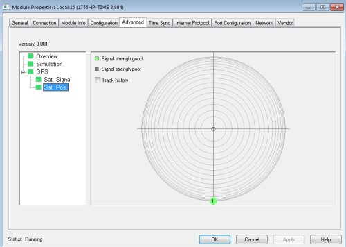
There are different options to create time synchronization within your ControlLogix system and there are modules that can help you stay synchronized automatically through GPS Antenna.

Here are a couple of examples and descriptions of what modules I am talking about:

TIME Modules

1756HP-TIME/1756-TIME

One way of keeping time is with a third party like Hiprom which makes a 1756HP-TIME module.  You can find documentation for configuration using the below link:

Or use the 1756-TIME module from Rockwell:

TIME Protocols

The above modules obtain their time from a GPS Antenna, and can synchronize with other modules using one of two different protocols:

1588 Precision Time Protocol (aka CIP Sync)

Enables high precision time synchronization over an EtherNet Network or the ControlLogix chassis backplane.

When PTP is selected, both EtherNet and Backplane synchronization are enabled.

NTP Protocol (Network Time Protocol)

Used for time synchronization with personal computers or domain controllers, this is configured with a HSNTP application that can be downloaded at http://www.ab.com.

The 1756-TIME Module supports NTP Version 3, RFC1305.

Synchronization Along the Backplane

Allen-Bradley 1756-EN2x Modules can use CIP Sync to synchronize with the grand clock Master as well as the ControlLogix Processor by enabling Time Synchronization under Controller Properties, or on the main tab of the Ethernet module’s configuration as shown in the following images:

  • Enabling Time Synchronization in Controller Properties

  • Enabling Time Synchronization in Ethernet Module Properties

Conclusion

Hopefully, this introduction to ControlLogix time synchronization will be beneficial to you and show you some of the available options if you are seeking precision time synchronization within or across your control systems.

Again, as listed above, a detailed explanation of this can be found in the Rockwell Publication 1756-um542_-en-p.pdf.

Good Luck in your endeavors ahead in TIME.

Written by Brandon Cooper
Senior Controls Engineer and Freelance Writer

Have a question? Join our community of pros to take part in the discussion! You'll also find all of our automation courses at TheAutomationSchool.com.

Sponsor and Advertise: Get your product or service in front of our 75K followers while also supporting independent automation journalism by sponsoring or advertising with us! Learn more in our Media Guide here, or contact us using this form.

shawntierney avatar
 

S7-1200FC – Failsafe Starter-Kit

Since the beginning of my career back in 2000, I have worked with quite a few different automation vendors and products.

The first PLC I ever touched was an old Allen Bradley SLC 100, and the next was a SLC 500. Then I was on the startup team for a facility with ControlLogix in 2002, and I have used a lot of it since.

Along the way I’ve also worked with Honeywell’s TDC 2000, TDC 3000, and Experion, and I even had a chance to work on an ABB Masterpiece DCS at one time.

But in all my years I’ve never had the opportunity to use or program a Siemens PLC.

Then recently, as part of my role as a freelancer writer for The Automation Blog, I was approached to see if I’d be interested in writing about using Siemens PLCs from the perspective of a first time user.

It sounded like a great opportunity to learn something new, so I agreed to document my journey trying to use and program Siemens PLCs from scratch, with no previous experience or exposure to their product line.

Now I should note that while I’m new to Siemens, The Automation Blog has covered Siemens quite a bit over the last couple of years, and you’ll find all of that previous coverage right here.

That said, I’m excited about starting my own journey and learning something new, and I’ll do my best to document everything I learn along the way, starting with the brand new S7-1200 Failsafe Starter Kit which just arrived:

To get started, below I’ll breakdown what’s included in the above S7-1200 Failsafe Starter Kit:

S7-1200 Failsafe Starter Kit:

  • A CPU 1212FC Firmware: V04.01.01
  • A Digital Input Module, 24 VDC
  • A Digital Output Module, RLY
  • Simulator Module
  • Simatic Step 7 Basic V16 License
  • Simatic Step 7 Safety Basic V16 License
  • Accessory Cabling Kit – Industrial EtherNet

Siemens also included two additional items with the kit:

  • Simatic Basic HMI
  • Book: Step 7 Programming by Stenerson\Deeg (highly recommend – ed.)

Some Assembly Required

The first step was to get the system components opened and assembled, so I unboxed everything, snapped the modules together, and mounted them on a piece of din rail.

Then I connected a 24vdc power supply to the controller and powered up the chassis:

Edit: I later learned that I also needed to power both Failsafe I/O modules with 24vdc as well – more about that in a future article!

Software Load

There is always a nervousness about loading software that you haven’t used before. You think to yourself, things like “What important step or option will I miss that I don’t know about?”

I will have to say, the software loads were very easy and went well. It was standard, click next, and move on.

With the S7-1200 unboxed and powered up and software installation completed, it’s time to get into the software and see what I can learn and put into place.

I will be reading the book that was sent to me “Siemens Step 7 (TIA PORTAL) Programming, a Practical Approach, 2nd Edition” along the way as well as the user manuals to guide me through the process.

As a final note I want to send out a big “Thank You” to Siemens and The Automation Blog for the opportunity to try out and share my journey using Siemens PLCs for the first time, and I can definitely say I’m looking forward to the journey ahead.

Written by Brandon Cooper
Senior Controls Engineer and Freelance Writer

Have a question? Join our community of pros to take part in the discussion! You'll also find all of our automation courses at TheAutomationSchool.com.

Sponsor and Advertise: Get your product or service in front of our 75K followers while also supporting independent automation journalism by sponsoring or advertising with us! Learn more in our Media Guide here, or contact us using this form.

shawntierney avatar
 

CCW – v13: What’s New Connected Components Workbench

Earlier this month Rockwell released version 13 of Connected Components Workbench, and today I’ll review the biggest new features as listed in the product’s release notes:

New Micro800 Features:

  • New “Controller Organizer” project tree style which makes CCW look a little more like Studio 5000 when the “Logix” Theme is selected. Note that when selected other devices (HMI, VFD, etc) will be hidden in this view
  • Controller Organizer view allows for the creation, editing, and deleting of Tasks, Programs, and Routines

  • The “lifecycle status” of Micro800 PLC’s are now shown when selecting them for use in your project:

  • The ability to “Verify” individual Micro800 programs without having to “Build” the entire project has been added
  • The “Graphical” Copy and Paste for the Ladder Editor has been enhanced
  • An improved “Data Grid” for quicker and more efficient declarations has been added
  • New Run Mode Change “Lite” is now supported and is suppose to allow logic changes without going to program mode
  • And the ability to import and export UDTs has been added

New PV800 Features:

  • Time Entry datatype support added for inputting time data
  • New “Object Explorer” view (like found in ViewStudio) added to aid users developing screens

  • New support added for the smallest CompactLogix 5380, the L306. Note that Firmware release 6.012 will be needed for the PV800 to support this feature

Enhanced features:

  • Document Generator can now create reports for Micro800 controller projects including programs, variables, ASCII text and configurations
  • Improved “find” function for text or string searches
  • PanelView 800 DesignStation… I don’t think this one is fleshed out yet as it’s called “PanelView 800 DesignStation” in the released notes, but the help (and website) still only lists PanelView Component(s) DesignStation (the old offline editor for PanelView Components HMIs.) I’ve reached out to Rockwell to see if they will come on my podcast and if they agree I’ll be sure to ask about this.
  • Animation config. with enhanced memory tag settings
  • Added multi-screen tab support to edit pane

Functional changes:

  • The Undo button does not always work with the new Data Grid (see release notes for details)
  • With the implementation of the new “Find” feature, the “Replace” function has been disabled for the current release
  • The “Build” function now only creates a “Full Build” the first time it is used, with subsequent clicks preforming “Incremental Builds.” To generate subsequent “Full Builds,” click on “Clean” before clicking on “Build”:

Learn about other releases:

Check out our coverage of other releases of CCW below:

Find out more:

If you would like to view the Connected Components Workbench 13.0 release notes, head over to Rockwell’s Product Versions webpage and search on the product “Connected Components,” then select Connected Components Workbench from the list.

Then from the versions page, click on the “PDF Document” icon under version 13.00.00:

So, what do you think of the new features of Connected Components Workbench 13?

Will you jump in and install v13 right away because of the added features or hardware support?

You can share your thoughts and opinions by joining our community at TheAutomationBlog.com/join.

Until next time, Peace ✌️ 

If you enjoy this episode please give it a Like, and consider Sharing as this is the best way for us to find new guests to come on the show.

Shawn M Tierney
Technology Enthusiast & Content Creator

Eliminate commercials and gain access to my weekly full length hands-on, news, and Q&A sessions by becoming a member at The Automation Blog or on YouTube. You'll also find all of my affordable PLC, HMI, and SCADA courses at TheAutomationSchool.com.

shawntierney avatar

Video Seasons On Sale – Save Up To 40%


Includes lifetime downloads and streaming!

Save even more with these coupons:

  • Buy any single season and save 25% with coupon code “Save25
  • Buy two or more seasons and save 40% with coupon code “Bundle40

The Automation Minute Season 1: $19.99 Sale: $14.99

Season one of The Automation Minute consists of Fifty Five episodes spanning two and a half hours. It also includes twelve bonus lessons. For more details and to purchase this season, click here. (see above coupons for additional savings!)

The Automation Minute Season 2: $19.99 Sale: $14.99

Season two of The Automation Minute consists of Fifty Three episodes spanning over three hours. It also includes one bonus lesson. For more details and to purchase this season, click here. (see above coupons for additional savings!)

The Automation Minute Season 3: $19.99 Sale: $14.99

Season three of The Automation Minute consists of Fifty Eight episodes spanning nearly four hours. For more details and to purchase this season, click here. (see above coupons for additional savings!)

The Automation Minute Season 4: $19.99 Sale: $14.99

Season four of The Automation Minute consists of over Thirty episodes spanning over two hours. For more details and to purchase this season, click here. (see above coupons for additional savings!)

The Automation Show Season 1: $39.99 Sale: $29.99

Season one of The Automation Show consists of over Fifty episodes spanning over sixteen hours. For more details and to purchase this season, click here. (see above coupons for additional savings!)


Until next time, Peace ✌️ 

If you enjoy this episode please give it a Like, and consider Sharing as this is the best way for us to find new guests to come on the show.

Shawn M Tierney
Technology Enthusiast & Content Creator

Eliminate commercials and gain access to my weekly full length hands-on, news, and Q&A sessions by becoming a member at The Automation Blog or on YouTube. You'll also find all of my affordable PLC, HMI, and SCADA courses at TheAutomationSchool.com.

shawntierney avatar

How To Setup & Use Moxa’s Remote Connection (MRC) Gateways (D005)

Learn how to use Moxa’s Remote Connection Gateways and Client Software in Episode 5 of The Automation Demo (originally episode 1 of Automation Tech Tips.)

For more information, check out the “Show Notes” located below the video.


The Automation Demo Episode 5 Show Notes (originally Tech Tips Episode 1:)

A huge thank you to Moxa for coming on Automation Tech Tips! For more information about their MRC products see the below links:


If you’re a vendor who’d like your product featured on our site or show, please contact us at: https://theautomationblog.com/guest

Until next time, Peace ✌️ 

If you enjoy this episode please give it a Like, and consider Sharing as this is the best way for us to find new guests to come on the show.

Shawn M Tierney
Technology Enthusiast & Content Creator

Eliminate commercials and gain access to my weekly full length hands-on, news, and Q&A sessions by becoming a member at The Automation Blog or on YouTube. You'll also find all of my affordable PLC, HMI, and SCADA courses at TheAutomationSchool.com.

shawntierney avatar

Industrial Raspberry Pi Project, Part 2

So, now I have a project and a target concept to build, I must dedicate myself fully to what components to use.

At this point, I have what feels like a lot of time, but I also know that this project will be broken into two main pieces…both of which could take a significant amount of time.

I feel pushing forward and staying as proactive as possible is the best way for me to get parts ordered and get the enclosure design underway.

I know I want a PC built into this system so that I can include an LCD touch display as well as interfacing for the mouse, keyboard, and a local monitor. With that in mind, the Raspberry Pi was immediately what I thought of.

I know the Pi isn’t really an industrial PC, but I didn’t want to go with the newest revision (model 4) due to my own personal experiences with industrial controls throughout my career.

Always wait a year or two (or until the next model) before integrating a “new” product into a system. A good guideline that has served me well.

I decided on the Pi 3.  After some quick research, I decided to use the higher frequency ARM of that series.  I chose the Raspberry Pi 3 B+ (64 bit and 1.4GHz).

From Part I, I know at least one key design aspect I don’t want to lose focus on.

  • Design housing at a targeted size of a mobile phone or a handheld digital camera

Sounds reasonable. With the Pi at the center of this design, its small footprint should make this a definite possibility.

Keeping that at the forefront of my choices, the best place I could find for getting easily integrated components (typically with sample code in Python) was Adafruit.  For Lady Ada and her examples, in the words of my favorite college professor, “You saved my life.”

For the key components, I chose the AMG8833 IR imaging device (Panasonic sensor with Adafruit package), the DHT22 ambient sensor, and a small camera.  I felt that these combined with the Raspberry Pi would make a nice system that could be compact as well.

I then set forth to use dimensions I could find for some components, as well as some I could only check as they arrived, to design the enclosure.  When looking back, this proved very beneficial in the overall project view.

As I put parts in and checked for fit and hole locations, I found some things that needed to be changed and tweaked.  If working towards a deadline, having the extra time to get some enclosure design tweaked is very helpful.

The first problem I made for myself was that I changed cameras from the original design concept to a much larger version.  At that moment, I thought it best to cover all my options, and having the IR and flash (or light) abilities seemed worth the risk.


This not only made the enclosure a little bigger (still within my set size limit) but posed a challenge on the inside when trying to mount it and fit other components around it.  I found that I needed to make the pillars (used for setting the threaded heat-set inserts in) as small as possible as well as using smaller bolts.

I tried using one size (4-40) as a standard throughout but had to decrease to 2-56 on the board mounting holes.  Also, I found that the camera MUST be put in first.

There just wasn’t the room to wiggle into position with the fan, PC, or other components in place.  The additional space created by stretching the enclosure for the camera did give me the ability to put in a cooling fan under the Raspberry Pi as well as the room to mount the power regulator for the 24 Vdc to 5 Vdc the Pi needed.

It took about two revisions to the solid model and 3D print trials to get it right.  But the enclosure modifications didn’t stop there. As I mounted the AMG8833, I found I just could not get the heat-set inserts in place correctly.

This required the need to step back and actually talk to my co-worker (my project designated mechanical engineer consultant).  The lid was modified from a flat fit to a wrap-around.  This allowed one side to be open leaving easier access to the placement for the heat-set inserts. This also gave me go-ahead to make the first higher quality print.

After the components were fit together and powered up, it was time to continue tweaking and improving.

I decided the lid needed to fit better, the camera needed protecting, I wanted heavy-duty mounting hardware, and I wanted to be sure the HDMI, USB, and Ethernet ports were accessible as well as able to be covered when not in use.

After a few more enclosure modifications and test prints to be sure holes, edges, and all accessibilities were as I wanted, the final fit and assembly was the next step.  As shown here, the system all fit together and powered up…but not without some steps to get the LCD to talk, other issues, and some changes to be made.

In the next installment, I’ll go over the last few physical changes as well as opportunities that started popping up with the power, wiring, and then on to the code.

Written by Paul Hunt
Senior Automation Engineer and Freelance Writer

Have a question? Join our community of pros to take part in the discussion! You'll also find all of our automation courses at TheAutomationSchool.com.

Sponsor and Advertise: Get your product or service in front of our 75K followers while also supporting independent automation journalism by sponsoring or advertising with us! Learn more in our Media Guide here, or contact us using this form.

shawntierney avatar