So, now I have a project and a target concept to build, I must dedicate myself fully to what components to use.
At this point, I have what feels like a lot of time, but I also know that this project will be broken into two main pieces…both of which could take a significant amount of time.
I feel pushing forward and staying as proactive as possible is the best way for me to get parts ordered and get the enclosure design underway.
I know I want a PC built into this system so that I can include an LCD touch display as well as interfacing for the mouse, keyboard, and a local monitor. With that in mind, the Raspberry Pi was immediately what I thought of.
I know the Pi isn’t really an industrial PC, but I didn’t want to go with the newest revision (model 4) due to my own personal experiences with industrial controls throughout my career.
Always wait a year or two (or until the next model) before integrating a “new” product into a system. A good guideline that has served me well.
I decided on the Pi 3. After some quick research, I decided to use the higher frequency ARM of that series. I chose the Raspberry Pi 3 B+ (64 bit and 1.4GHz).
From Part I, I know at least one key design aspect I don’t want to lose focus on.
- Design housing at a targeted size of a mobile phone or a handheld digital camera
Sounds reasonable. With the Pi at the center of this design, its small footprint should make this a definite possibility.
Keeping that at the forefront of my choices, the best place I could find for getting easily integrated components (typically with sample code in Python) was Adafruit. For Lady Ada and her examples, in the words of my favorite college professor, “You saved my life.”
For the key components, I chose the AMG8833 IR imaging device (Panasonic sensor with Adafruit package), the DHT22 ambient sensor, and a small camera. I felt that these combined with the Raspberry Pi would make a nice system that could be compact as well.

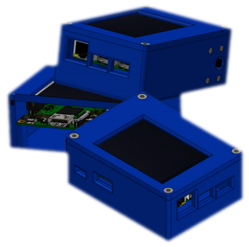
I then set forth to use dimensions I could find for some components, as well as some I could only check as they arrived, to design the enclosure. When looking back, this proved very beneficial in the overall project view.
As I put parts in and checked for fit and hole locations, I found some things that needed to be changed and tweaked. If working towards a deadline, having the extra time to get some enclosure design tweaked is very helpful.
The first problem I made for myself was that I changed cameras from the original design concept to a much larger version. At that moment, I thought it best to cover all my options, and having the IR and flash (or light) abilities seemed worth the risk.
This not only made the encl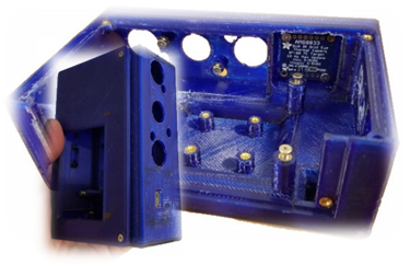 osure a little bigger (still within my set size limit) but posed a challenge on the inside when trying to mount it and fit other components around it. I found that I needed to make the pillars (used for setting the threaded heat-set inserts in) as small as possible as well as using smaller bolts.
I tried using one size (4-40) as a standard throughout but had to decrease to 2-56 on the board mounting holes. Also, I found that the camera MUST be put in first.
There just wasn’t the room to wiggle into position with the fan, PC, or other components in place. The additional space created by stretching the enclosure for the camera did give me the ability to put in a cooling fan under the Raspberry Pi as well as the room to mount the power regulator for the 24 Vdc to 5 Vdc the Pi needed.
It took about two revisions to the solid model and 3D print trials to get it right. But the enclosure modifications didn’t stop there. As I mounted the AMG8833, I found I just could not get the heat-set inserts in place correctly.
This required the need to step back and actually talk to my co-worker (my project designated mechanical engineer consultant). The lid was modified from a flat fit to a wrap-around. This allowed one side to be open leaving easier access to the placement for the heat-set inserts. This also gave me go-ahead to make the first higher quality print.
After the components were fit together and powered up, it was time to continue tweaking and improving.
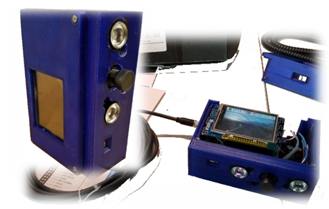
I decided the lid needed to fit better, the camera needed protecting, I wanted heavy-duty mounting hardware, and I wanted to be sure the HDMI, USB, and Ethernet ports were accessible as well as able to be covered when not in use.
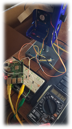
After a few more enclosure modifications and test prints to be sure holes, edges, and all accessibilities were as I wanted, the final fit and assembly was the next step. As shown here, the system all fit together and powered up…but not without some steps to get the LCD to talk, other issues, and some changes to be made.
In the next installment, I’ll go over the last few physical changes as well as opportunities that started popping up with the power, wiring, and then on to the code.
Written by Paul Hunt
Senior Automation Engineer and Freelance Writer
Have a question? Join our community of pros to take part in the discussion! You'll also find all of our automation courses at TheAutomationSchool.com.
Sponsor and Advertise: Get your product or service in front of our 75K followers while also supporting independent automation journalism by sponsoring or advertising with us! Learn more in our Media Guide here, or contact us using this form.
- Mitsubishi PLCs: Brief History and Hardware Overview - August 2, 2022
- Mitsubishi PLCs: FX5 vs iQ-R - February 10, 2022
- How To Register and Use a Device Profile in GX Works3 - November 9, 2021

Discover more from The Automation Blog
Subscribe to get the latest posts sent to your email.


