In part three of my nine part series covering new PLC and HMI products shown at Automation Fair 2017, I discuss the newly announced 1756 Compute Module (Episode 10 of The Automation Minute Season 4:)
If you’ve found this video helpful, checkout my training courses here.
Check out our Video Collection #1 here, which includes the first five seasons of our shows for just $30!
Until next time, Peace ✌️
If you enjoy this episode please give it a Like, and consider Sharing as this is the best way for us to find new guests to come on the show.
Eliminate commercials and gain access to my weekly full length hands-on, news, and Q&A sessions by becoming a member at The Automation Blog or on YouTube. You'll also find all of my affordable PLC, HMI, and SCADA courses at TheAutomationSchool.com.
I'm a lifelong Technology Enthusiast who began programing in the early 80's on the Apple II and VIC-20 personal computers. After earning a degree in Electronics, I worked as a Certified Controls and Information Automation Specialist for 25 years before leaving to become a full time Industrial Automation instructor and mentor at TheAutomationSchool, as well as publishing industry interviews, news, and product how-to’s at TheAutomationBlog.com. If you're interested in my training, mentoring, or becoming a sponsor, please schedule a teams meeting with me via https://calendly.com/shawntierney/business-meeting
In part two of my nine part series covering new PLC and HMI products shown at Automation Fair 2017, I discuss the newly announced Studio 5000 refresh coming this month (Episode 9 of The Automation Minute Season 4:)
If you’ve found this video helpful, checkout my training courses here.
Check out our Video Collection #1 here, which includes the first five seasons of our shows for just $30!
Until next time, Peace ✌️
If you enjoy this episode please give it a Like, and consider Sharing as this is the best way for us to find new guests to come on the show.
Eliminate commercials and gain access to my weekly full length hands-on, news, and Q&A sessions by becoming a member at The Automation Blog or on YouTube. You'll also find all of my affordable PLC, HMI, and SCADA courses at TheAutomationSchool.com.
I'm a lifelong Technology Enthusiast who began programing in the early 80's on the Apple II and VIC-20 personal computers. After earning a degree in Electronics, I worked as a Certified Controls and Information Automation Specialist for 25 years before leaving to become a full time Industrial Automation instructor and mentor at TheAutomationSchool, as well as publishing industry interviews, news, and product how-to’s at TheAutomationBlog.com. If you're interested in my training, mentoring, or becoming a sponsor, please schedule a teams meeting with me via https://calendly.com/shawntierney/business-meeting
Welcome to part four of the nine part series covering my picks for the top new PLC and HMI products shown at Rockwell’s Automation Fair 2017.
Note: While this series covers the products in which I’m most interested, you’ll find all the new products listed in Rockwell’s guide HERE.
Connected Components Workbench R11:
Due out in February 2018, Rockwell’s “Connected Components Workbench” software is set to get a major makeover.
The goal? To provide CCW users an experience closer to that of Studio 5000 Logix Designer.
This makeover is said to be achieved through updated workflows, defaults, color schemes, and sounds that resemble their equivalents in Studio 5000.
They are also adding a new “theme” feature, so you can display instructions in either the existing IEC format, or with the instructions names used in Studio 5000.
Also included is support for copying and pasting ladder logic from RSLogix 500 and Studio 5000 directly into CCW.
This, along with new “RSLogix” like toolbars, and the ability to enter rungs of ladder using text entry, should be welcome additions for RSLogix and Studio 5000 users.
Finally, to the above interface changes, CCW R11 also aims to add hardware support for the Micro870, E200 OL Relay, 450L-E Light Curtain and PF755T drive.
If you’d like to know more check out Thomas Sugimoto’s video below:
So what do you think?
Personally, while I’ve grown attached to CCW R10 (especially FBD,) I’m curious about what this new version will look like (will it really look like Studio 5000?)
How about you?
Will you be considering CCW for the first time with release 11?
Or are you already using a previous version?
Please feel free to share your thoughts with us by clicking on the “post a comment or question” link below.
Until next time, Peace ✌️
If you enjoy this episode please give it a Like, and consider Sharing as this is the best way for us to find new guests to come on the show.
Eliminate commercials and gain access to my weekly full length hands-on, news, and Q&A sessions by becoming a member at The Automation Blog or on YouTube. You'll also find all of my affordable PLC, HMI, and SCADA courses at TheAutomationSchool.com.
I'm a lifelong Technology Enthusiast who began programing in the early 80's on the Apple II and VIC-20 personal computers. After earning a degree in Electronics, I worked as a Certified Controls and Information Automation Specialist for 25 years before leaving to become a full time Industrial Automation instructor and mentor at TheAutomationSchool, as well as publishing industry interviews, news, and product how-to’s at TheAutomationBlog.com. If you're interested in my training, mentoring, or becoming a sponsor, please schedule a teams meeting with me via https://calendly.com/shawntierney/business-meeting
Welcome to part three of the nine part series detailing my picks for the top new PLC and HMI products shown at Rockwell’s Automation Fair 2017.
Note: While this series covers the products in which I’m most interested, you’ll find all the new products listed in Rockwell’s guide HERE.
The New 1756 Compute Module:
Due out this month, Rockwell describes the 1756 Compute Module as an embedded Windows 10 module with high-speed computing functionality.
This, along with high-speed backplane access to ControlLogix controllers (via included API,) is said to allow real-time calculations and decision making, all while supporting Windows 10 IoT applications.
That’s about all the Automation Fair information provided, but I was able to find additional details from the recently published 1756-IN072 installation instructions.
UPDATE – Received more information about the CPU and Memory: The module contains a Intel Atom 1.46 GHz dual core processor, 4 GB RAM, and a 32 GB SSD (approx. 20 GB free space for user applications.)
First, it appears the module will actually come in two versions:
1756-CMS1B1 module – Windows 10IoT Enterprise 64-bit OS
1756-CMS1C1 module – Linux OS 32-bit
These modules also appear to come with two Gigabit Ethernet Ports, one USB 3.0 port, and an integrated DisplayPort connector behind a door under the modules status display.
Below are links to the installation instructions and (soon to be released?) user manual:
While this latest “Computer in a Module” offering looks interesting, I’m not sure there is a very large market for it?
Since the release of the 1771-DSX2 and 4 modules, I’ve seen many iterations of these modules come out, but haven’t found the right application in which to use them.
While they undoubtedly save panel space, the expense of previous models didn’t justify the space savings.
For instance, one of the previous “computer in a slot” products cost nearly $10K, and had specs that were a full magnitude lower than the typical $3K Industrial PC.
That said, only time will tell if this latest version of the “PC in a Module” concept will have more success that its predecessors.
So what do you think?
Will you consider the above product, or does it not have a place in your facility?
Please feel free to share your thoughts with us by clicking on the “post a comment or question” link below.
Until next time, Peace ✌️
If you enjoy this episode please give it a Like, and consider Sharing as this is the best way for us to find new guests to come on the show.
Eliminate commercials and gain access to my weekly full length hands-on, news, and Q&A sessions by becoming a member at The Automation Blog or on YouTube. You'll also find all of my affordable PLC, HMI, and SCADA courses at TheAutomationSchool.com.
I'm a lifelong Technology Enthusiast who began programing in the early 80's on the Apple II and VIC-20 personal computers. After earning a degree in Electronics, I worked as a Certified Controls and Information Automation Specialist for 25 years before leaving to become a full time Industrial Automation instructor and mentor at TheAutomationSchool, as well as publishing industry interviews, news, and product how-to’s at TheAutomationBlog.com. If you're interested in my training, mentoring, or becoming a sponsor, please schedule a teams meeting with me via https://calendly.com/shawntierney/business-meeting
Welcome to part two of the nine part series detailing my picks for the top new PLC and HMI products shown at Rockwell’s Automation Fair 2017.
Note: While this series covers the products in which I’m most interested, you’ll find all the new products listed in Rockwell’s guide HERE.
The New Studio 5000:
Due out this month, Rockwell’s releasing an updated user interface for Studio 5000 to provide what they say will be a common look across all Studio 5000 applications.
While I was unable to find pictures of the redesign online, and no new release of Studio 5000 were available earlier this week, Rockwell states this “soon to be released” version of Studio 5000 Logix Designer has improved workflows when used with multi-monitors, as well as improved tabbed views.
In addition, Rockwell stated that they have updated several of Logix Designer’s programming languages to optimize programming time, which I’m interpreting to mean less clicks and more efficient programming.
Moving on to View Designer, it is said to now include native Data Logging and Trending, something I think its needed for awhile as most other modern HMIs have had those features.
View Designer is also said to be getting an “Emulation Mode,” which I hope is similar to what’s been available in ViewStudio since it launched (and was in RSView before it.)
Studio 5000 Architect gets new “AutomationML” capabilities for bidirectional exchange of data between engineering tools and Studio 5000.
And finally, the Studio 5000 Application Code Manager is said to have had a “Class View” added to allow for viewing library content which crosses Logix content.
So what do you think?
Will you consider the above product, or does it not have a place in your facility?
Please feel free to share your thoughts with us by clicking on the “post a comment or question” link below.
Until next time, Peace ✌️
If you enjoy this episode please give it a Like, and consider Sharing as this is the best way for us to find new guests to come on the show.
Eliminate commercials and gain access to my weekly full length hands-on, news, and Q&A sessions by becoming a member at The Automation Blog or on YouTube. You'll also find all of my affordable PLC, HMI, and SCADA courses at TheAutomationSchool.com.
I'm a lifelong Technology Enthusiast who began programing in the early 80's on the Apple II and VIC-20 personal computers. After earning a degree in Electronics, I worked as a Certified Controls and Information Automation Specialist for 25 years before leaving to become a full time Industrial Automation instructor and mentor at TheAutomationSchool, as well as publishing industry interviews, news, and product how-to’s at TheAutomationBlog.com. If you're interested in my training, mentoring, or becoming a sponsor, please schedule a teams meeting with me via https://calendly.com/shawntierney/business-meeting
In part one of my nine part series featuring new products shown at Automation Fair 2017, I discuss the newly released PanelView 5310 (Episode 8 of The Automation Minute Season 4:):
If you’ve found this video helpful, checkout my training courses here.
Check out our Video Collection #1 here, which includes the first five seasons of our shows for just $30!
Until next time, Peace ✌️
If you enjoy this episode please give it a Like, and consider Sharing as this is the best way for us to find new guests to come on the show.
Eliminate commercials and gain access to my weekly full length hands-on, news, and Q&A sessions by becoming a member at The Automation Blog or on YouTube. You'll also find all of my affordable PLC, HMI, and SCADA courses at TheAutomationSchool.com.
I'm a lifelong Technology Enthusiast who began programing in the early 80's on the Apple II and VIC-20 personal computers. After earning a degree in Electronics, I worked as a Certified Controls and Information Automation Specialist for 25 years before leaving to become a full time Industrial Automation instructor and mentor at TheAutomationSchool, as well as publishing industry interviews, news, and product how-to’s at TheAutomationBlog.com. If you're interested in my training, mentoring, or becoming a sponsor, please schedule a teams meeting with me via https://calendly.com/shawntierney/business-meeting
Welcome to part one of my nine part series detailing my picks for the top new PLC and HMI products shown at Rockwell’s Automation Fair 2017.
Note: While this series covers the new products I’m most interested in, you’ll find all the new products listed in Rockwell’s guide HERE.
The New PanelView 5310:
According to Rockwell’s sales literature, this new addition to the PanelView 5000 family became available for sale this week.
Touted as providing the same seamless integration as the PanelView 5500 series HMI, this line is targeted at smaller “Touch Only” machine builder applications in the 6”, 7”, 9” and 12” screen size.
And as with the PanelView 5500 series, the 5310 series is programmed with Studio 5000’s View Designer design environment which Rockwell states offers seamless integration with Studio 5000 Logix Designer and Rockwell’s Logix series of PACs.
For additional information, check out Sue Burtch’s video below:
So what do you think?
Will you consider the above product, or does it not have a place in your facility?
Please feel free to share your thoughts with us by clicking on the “post a comment or question” link below.
Until next time, Peace ✌️
If you enjoy this episode please give it a Like, and consider Sharing as this is the best way for us to find new guests to come on the show.
Eliminate commercials and gain access to my weekly full length hands-on, news, and Q&A sessions by becoming a member at The Automation Blog or on YouTube. You'll also find all of my affordable PLC, HMI, and SCADA courses at TheAutomationSchool.com.
I'm a lifelong Technology Enthusiast who began programing in the early 80's on the Apple II and VIC-20 personal computers. After earning a degree in Electronics, I worked as a Certified Controls and Information Automation Specialist for 25 years before leaving to become a full time Industrial Automation instructor and mentor at TheAutomationSchool, as well as publishing industry interviews, news, and product how-to’s at TheAutomationBlog.com. If you're interested in my training, mentoring, or becoming a sponsor, please schedule a teams meeting with me via https://calendly.com/shawntierney/business-meeting
In today’s article I’ll walk you through how to download Rockwell and Allen-Bradley software updates for purchased software.
NOTE: If you need to download free software like RSLinx Classic Lite, you can skip to step 2, and in Step 3 choose “Find Downloads” to search for the software you wish to download.
You will still have to log in (as shown in Step 4,) after searching for and selecting to download the free software, but you won’t need to provide a serial number.
Step 1) The first step is to locate your Activation Certificate.
If you purchases a Disc copy, the certificate will be in a red envelope. If you purchased a digital copy, you will have received a digital certificate via email:
Below you can see a copy of a physical activation certificate. The digital “email” version has the same information:
Step 2) Now point your browser at http://www.AB.com, and once there click on the “Compatibility & Downloads” link:
Step 3) Next, click on “Software Downloads by Serial Number”:
Step 4) At this point you will be asked to log into Rockwell’s website. If you don’t have a Rockwell website login, click on “Sign up now” and sign-up for a free Rockwell website account:
Step 5) Once you’re signed in, the next page asks you to enter in your serial number and either your product key, company name, order no, company no, or BPID as shown below:
Step 6) Enter in the Serial Number and Product Key from your Activation Certificate and then click on Next.
Step 7) Now you should see the package in question listed along with a drop down list showing the versions available to you, as well as any additional downloads:
NOTE: If you don’t have a support contract you will only see up to the last version you had support for, or the latest version available when you purchased the software.
Step 8) Go ahead and select the version you wish to download and click on the blue download arrow, at which point you’ll need to also accept the license agreement:
Step 9) And then select “Direct Download:”
Step 10) And finally select each of the blue links for your downloads:
If you’d like to watch a video demonstration of the above, check out Episode 18 of The Automation Minute Season 4 below:
I hope you’ve found the above information on how to download Rockwell Automation software updates helpful.
If you have any questions or would like to comment on the above article please feel free to click on the “post a comment or question” link below.
Until next time, Peace ✌️
If you enjoy this episode please give it a Like, and consider Sharing as this is the best way for us to find new guests to come on the show.
Eliminate commercials and gain access to my weekly full length hands-on, news, and Q&A sessions by becoming a member at The Automation Blog or on YouTube. You'll also find all of my affordable PLC, HMI, and SCADA courses at TheAutomationSchool.com.
I'm a lifelong Technology Enthusiast who began programing in the early 80's on the Apple II and VIC-20 personal computers. After earning a degree in Electronics, I worked as a Certified Controls and Information Automation Specialist for 25 years before leaving to become a full time Industrial Automation instructor and mentor at TheAutomationSchool, as well as publishing industry interviews, news, and product how-to’s at TheAutomationBlog.com. If you're interested in my training, mentoring, or becoming a sponsor, please schedule a teams meeting with me via https://calendly.com/shawntierney/business-meeting
If you didn’t attend Rockwell Automation’s TechED this year, you’ll be happy to know that the good folks over at Rockwell have made the majority of the presentation and lab manual downloads available free of charge.
Unfortunately, it’s not super easy to find these downloads, so in today’s article I show you how:
1) Start by visiting http://www.RSTechED.com, which redirects you to the official Rockwell Automation TechED home page:
2) From there select “Rockwell Automation TechED” from the list on the right:
3) Now select the “Desktop Portal” link:
4) And once it loads, select “Schedule” on the left:
5) From here select a session on the left, and if there are downloads for that session they will show up on the right as seen below:
6) Select the download you are interested in, and then click on the download link at the top right of the popup window:
And that’s all there is to accessing this year’s Rockwell Automation TechED presentations and labs for free!
I hope you’ve found today’s article about downloading this year’s TechED labs and presentations helpful.
If you have any comments, questions, or suggestions, please feel free to leave them with us by clicking the “post a comment or question” link below.
Until next time, Peace ✌️
If you enjoy this episode please give it a Like, and consider Sharing as this is the best way for us to find new guests to come on the show.
Eliminate commercials and gain access to my weekly full length hands-on, news, and Q&A sessions by becoming a member at The Automation Blog or on YouTube. You'll also find all of my affordable PLC, HMI, and SCADA courses at TheAutomationSchool.com.
I'm a lifelong Technology Enthusiast who began programing in the early 80's on the Apple II and VIC-20 personal computers. After earning a degree in Electronics, I worked as a Certified Controls and Information Automation Specialist for 25 years before leaving to become a full time Industrial Automation instructor and mentor at TheAutomationSchool, as well as publishing industry interviews, news, and product how-to’s at TheAutomationBlog.com. If you're interested in my training, mentoring, or becoming a sponsor, please schedule a teams meeting with me via https://calendly.com/shawntierney/business-meeting
In today’s article I review how to add a momentary “Start-up Splash Screen” to a FactoryTalk View Studio Machine Edition project without using PLC logic as we did in yesterday’s article.
One of our readers at TheAutomationForums recently asked how he could add a “start-up splash screen” to his PanelView Plus that would display his company’s logo for a few seconds, before switching to the project’s main menu.
In today’s article I’ll show how to do this without using PLC code like we did yesterday. Instead we’ll use FactoryTalk View Macros.
Steps to be taken:
The steps we need to take to complete this object are as follows:
We need to detect when the PanelView launches our project, and we can do this by setting our start-up splash screen as the default display, and giving that display a unique display number, which in our example is 99.
After the set period of time has elapsed, we need to command the HMI to display our main screen, which in this example will have a display number of 1 (no other displays can have a display number of 1 or 99)
Once the main screen is displayed, we need to release screen control to the operators so they navigate the HMI.
Step 1) Our first step is to open the “HMI Tag Editor” and create two HMI memory tags, both of which I’ll put into a new “Memory” HMI tag folder.
The first tag is named “StartUpTime” with the settings shown below:
The second tag is named “DisplayControl” with the settings shown below:
Step 2) Next, we close the “HMI Tag Editor” and open “Global Connections.” Then we set the “Remote Display Number” to our new “Display Control” tag, and click on “OK” to save our changes:
Step 3) Next, we open each of our project’s Graphic Displays and insure they each have a unique “Display Number.” This setting is found in the “General” tab of “Display Settings” which is found in the “Edit” and “Right Click” menus when the “Graphic Display” is selected:
Step 4) Now that we’ve updated and saved all our graphic displays, we next open “Startup” and insure our start-up splash screen display is set as the initial graphic. In this example that screen is named “LOGO.” Once done we click on “OK” to save our settings:
Step 5) At this point we need to create our first new Macro:
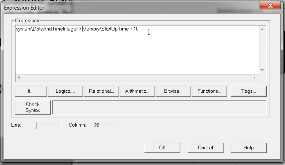
Step 6) This macro will have a Tag of “Memory\StartupTime” and an expression of “system\DateAndTimeInteger,” as shown below:
Step 7) The we save this new Macro as “StartUpMacro::
NOTE: You can purchase “ad free” copies of our articles, videos, and sample code for $1 each here.
Step 8) Now we return to “Startup” and select our new “StartUpMacro” as our “Startup Macro,” as shown below:
Step 9) From there we head over to Global Connections again, and this time we go to the “Macro” tab:
Step 10) Under “Remote Macro 1” we add the following expression as our trigger and click “OK” twice to save it:
Step 11) We now need to create two more Macros. The first has a tag of “Memory\DisplayControl” and a value of 1, and must be saved with a name of “Macro1”:
Step 12) The next has a tag of “Memory\DisplayControl” and a value of 0, and is saved as “StartUpDoneMacro”
Step 13) The last step is to open our “main” screen (with a display number of 1) and set the “Display Settings – Behavior” to use a Startup Macro of our new “StartUpDoneMacro,” as shown below:
Step 14) Now when we run our project, our “LOGO” start-up splash screen will be displayed for ten seconds:
Step 15) After which our “main” screen will be displayed, and the “Remote Display Number” will be reset to 0 to allow operator navigation control:
If you’d like to watch a video demonstration of the above, check out Episode 7 of The Automation Minute Season 4 below:
Have a question or comment? Please feel free to ask me here.
Until next time, Peace ✌️
If you enjoy this episode please give it a Like, and consider Sharing as this is the best way for us to find new guests to come on the show.
Eliminate commercials and gain access to my weekly full length hands-on, news, and Q&A sessions by becoming a member at The Automation Blog or on YouTube. You'll also find all of my affordable PLC, HMI, and SCADA courses at TheAutomationSchool.com.
I'm a lifelong Technology Enthusiast who began programing in the early 80's on the Apple II and VIC-20 personal computers. After earning a degree in Electronics, I worked as a Certified Controls and Information Automation Specialist for 25 years before leaving to become a full time Industrial Automation instructor and mentor at TheAutomationSchool, as well as publishing industry interviews, news, and product how-to’s at TheAutomationBlog.com. If you're interested in my training, mentoring, or becoming a sponsor, please schedule a teams meeting with me via https://calendly.com/shawntierney/business-meeting
In today’s article I review how to add a PLC controlled “Start-up Splash Screen” to your FactoryTalk View Studio Machine Edition project.
Recently, one of our readers from TheAutomationForums asked how he could add a start-up splash screen to his PanelView Plus that would display his company’s logo for a few seconds before switching to the projects main menu.
In today’s article I’ll demonstrate how to do this using a PLC, and in tomorrow’s article I’ll show how to do this without using a PLC.
Steps to be taken:
The steps we need to take to complete this project are as follows:
We need to detect when the PanelView launches our project – we can do this by setting our start-up splash screen as the default display, and giving that display a unique “display number,” which in our example is 99.
After the set period of time has elapsed, we need to command the HMI to display our “main” screen, which in this example will have a display number of 1 (no other displays can have a display number of 1 or 99 for our example to work)
Once the main screen is displayed, we need to release screen control to the operators so they navigate the HMI.
Step 1) With your existing HMI project open in FactoryTalk View Studio, create and save your “Start-up Splash Screen” Graphic Display with a unique Display Number. In this example we named our start-up screen “LOGO” and gave it a display number of 99.
Step 2) Now open the screen you want to automatically replace the start-up screen (i.e. your “main” display,) and set its “Display Number.” In this example we display our “Main Menu” graphic display and gaven it a “Display Number” of 1.
NOTE: You’ll want to insure your remaining screens all have unique display numbers, or at a very minimum do not have the same display number as your start-up and main screens.
Step 3) Now open the “Startup” settings and make your new start-up splash screen your “Initial Graphic,” and then click on “OK” to save your changes:
Step 4) Next open “Global Connections,” select the “Display” tab, and then:
Provide a unique PLC Tag / Address for the “Replace Display Number.” The PanelView Plus will write the currently display Graphic Display number to this PLC tag.
Provide a unique PLC Tag / Address for the “Remote Display Number.” The PanelView Plus will read this tag value and if it’s a valid display number, the PVPlus will display the corresponding Graphic Display.
Step 5) Now that the HMI is configure, the next step is to add the control code to the PLC. Shown below are the two rungs used in this example:
NOTE: You can purchase “ad free” copies of our articles, videos, and sample code for $1 each here. Or become a “Patron” for as little as $1 a month and receive at least $3 worth of articles/videos/sample code free each month! Find out more here.
Step 6) The first rung detects when our startup screen is being displayed by comparing the “Replace Display Number” tag (N7:1) with a constant that represents the “Display Number” we gave our start-up screen (99.)
Note: By design we only display the start-up screen when the PanelView Plus first starts our application, as set in Step 2 above.
When our start-up graphic is being displayed, a timer starts for however long we want our start-up screen displayed:
Step 7) When the timer is done, the code calls for our main menu to be displayed by moving a 1 into the “Remote Display Number” tag (N7:0):
Step 8) When our second rung detects the code is commanding display 1 (N7:0,) and the PanelView Plus is also displaying that same screen (indicated by a 1 in the replace screen tag of N7:1) the rung then moves a 0 into the “Remote Display Number” tag (N7:0):
Step 9) And once the “Remote Display Number” tag (N7:0) is 0, the operator gains the ability to navigate HMI displays:
If you’d like to watch a video demonstration of the above, check out Episode 6 of The Automation Minute Season 4 below:
Have a question or comment? Please feel free to ask me here.
Until next time, Peace ✌️
If you enjoy this episode please give it a Like, and consider Sharing as this is the best way for us to find new guests to come on the show.
Eliminate commercials and gain access to my weekly full length hands-on, news, and Q&A sessions by becoming a member at The Automation Blog or on YouTube. You'll also find all of my affordable PLC, HMI, and SCADA courses at TheAutomationSchool.com.
I'm a lifelong Technology Enthusiast who began programing in the early 80's on the Apple II and VIC-20 personal computers. After earning a degree in Electronics, I worked as a Certified Controls and Information Automation Specialist for 25 years before leaving to become a full time Industrial Automation instructor and mentor at TheAutomationSchool, as well as publishing industry interviews, news, and product how-to’s at TheAutomationBlog.com. If you're interested in my training, mentoring, or becoming a sponsor, please schedule a teams meeting with me via https://calendly.com/shawntierney/business-meeting
Eliminate commercials and gain access to my weekly full length hands-on, news, and Q&A sessions by becoming a member at The Automation Blog or on YouTube. You'll also find all of my affordable PLC, HMI, and SCADA courses at TheAutomationSchool.com.
I'm a lifelong Technology Enthusiast who began programing in the early 80's on the Apple II and VIC-20 personal computers. After earning a degree in Electronics, I worked as a Certified Controls and Information Automation Specialist for 25 years before leaving to become a full time Industrial Automation instructor and mentor at TheAutomationSchool, as well as publishing industry interviews, news, and product how-to’s at TheAutomationBlog.com. If you're interested in my training, mentoring, or becoming a sponsor, please schedule a teams meeting with me via https://calendly.com/shawntierney/business-meeting
In today’s article I review how to remotely trigger Graphic Displays on a PanelView Plus or FactoryTalk View Machine Edition Runtime.
Step 1) With your View Studio project open, double click on Global Connections:
Step 2) Now select the “Display” tab:
Step 3) Here you need to provide a Tag for the “Remote Display Number” Global Connection, which will be used to control which Graphic Display is shown:
NOTE: You can purchase “ad free” copies of our articles, videos, and sample code for $1 each here. Or become a “Patron” for as little as $1 a month and receive at least $3 worth of articles/videos/sample code free each month! Find out more here.
Step 4) After you’ve selected your Tag click on “OK” in the Tag Browser, and “OK” again in Global Connections to save your selection:
Step 5) Now open and check each of your Graphic Displays to be sure they all have a unique “Display Number” setting. This is done in the “Display Settings” for each screen, which can be access from the “Edit” and right-click menus:
Step 6) In the below example, the display shown has a “Display Number” setting of 1:
Step 7) With the above changes complete, run your project. Then when you enter the corresponding value into your “Remote Display Number” tag, the HMI will display that graphic display and will stay there until you change your “Remote Display Number” tag to another value.
NOTE: To allow the operator to freely navigate the HMI project, be sure to set the “Remote Display Number” tag’s value to 0.
Also, if your “Remote Display Number” tag’s value doesn’t correspond to any Graphic Display, you’ll receive an error on the HMI.
If you’d like to watch a video demonstration of the above, check out Episode 5 of The Automation Minute Season 4 below:
Have a question or comment? Please feel free to ask me here.
Until next time, Peace ✌️
If you enjoy this episode please give it a Like, and consider Sharing as this is the best way for us to find new guests to come on the show.
Eliminate commercials and gain access to my weekly full length hands-on, news, and Q&A sessions by becoming a member at The Automation Blog or on YouTube. You'll also find all of my affordable PLC, HMI, and SCADA courses at TheAutomationSchool.com.
I'm a lifelong Technology Enthusiast who began programing in the early 80's on the Apple II and VIC-20 personal computers. After earning a degree in Electronics, I worked as a Certified Controls and Information Automation Specialist for 25 years before leaving to become a full time Industrial Automation instructor and mentor at TheAutomationSchool, as well as publishing industry interviews, news, and product how-to’s at TheAutomationBlog.com. If you're interested in my training, mentoring, or becoming a sponsor, please schedule a teams meeting with me via https://calendly.com/shawntierney/business-meeting
Eliminate commercials and gain access to my weekly full length hands-on, news, and Q&A sessions by becoming a member at The Automation Blog or on YouTube. You'll also find all of my affordable PLC, HMI, and SCADA courses at TheAutomationSchool.com.
I'm a lifelong Technology Enthusiast who began programing in the early 80's on the Apple II and VIC-20 personal computers. After earning a degree in Electronics, I worked as a Certified Controls and Information Automation Specialist for 25 years before leaving to become a full time Industrial Automation instructor and mentor at TheAutomationSchool, as well as publishing industry interviews, news, and product how-to’s at TheAutomationBlog.com. If you're interested in my training, mentoring, or becoming a sponsor, please schedule a teams meeting with me via https://calendly.com/shawntierney/business-meeting
In today’s article I review how to use RSLinx Classic Lite and RSEmulate 500 with FactoryTalk View Studio.
Not many users know that FactoryTalk View Machine Edition projects can be tested using the free versions of RSLinx Classic and RSEmulate 500 (for instructions on how to download both, check out my previous article here)
The only requirement is you must have a licensed copy of FactoryTalk View Studio OR a licensed copy of RSLinx Classic.
If both packages are demo versions, then the below procedure will likely fail as OPC will not be enabled.
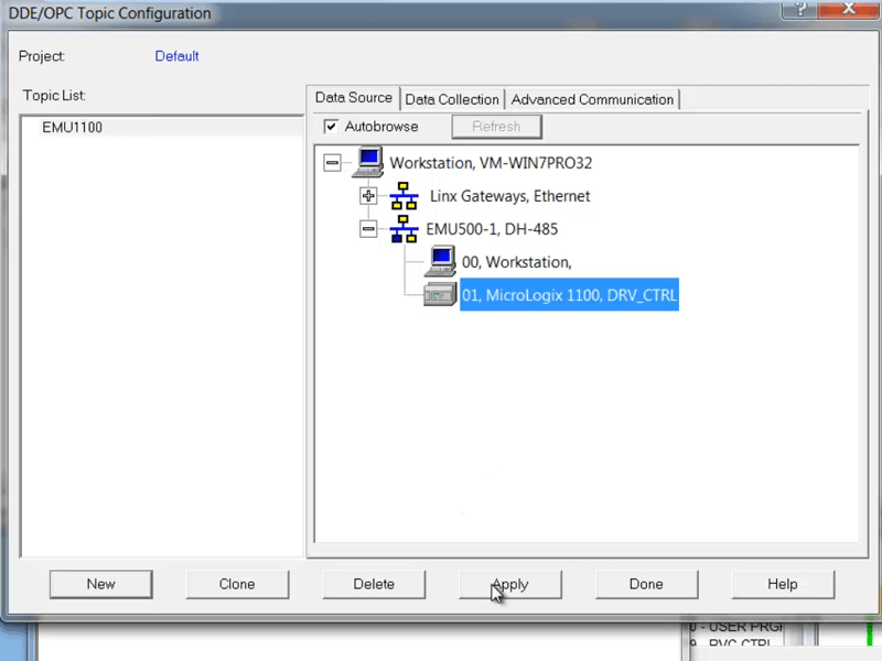
Step 1) With RSLinx open and connected to your emulated PLC, select “Topic Configuration” from the “DDE/OPC Menu”:
Step 2) Next, select your emulated PLC from the RSWho window:
Step 3) Now click on “New”:
Step 4) And enter in a name for your new “Topic.” In this example I entered in a name of “EMU1100”:
Step 5) Then click on “Apply”:
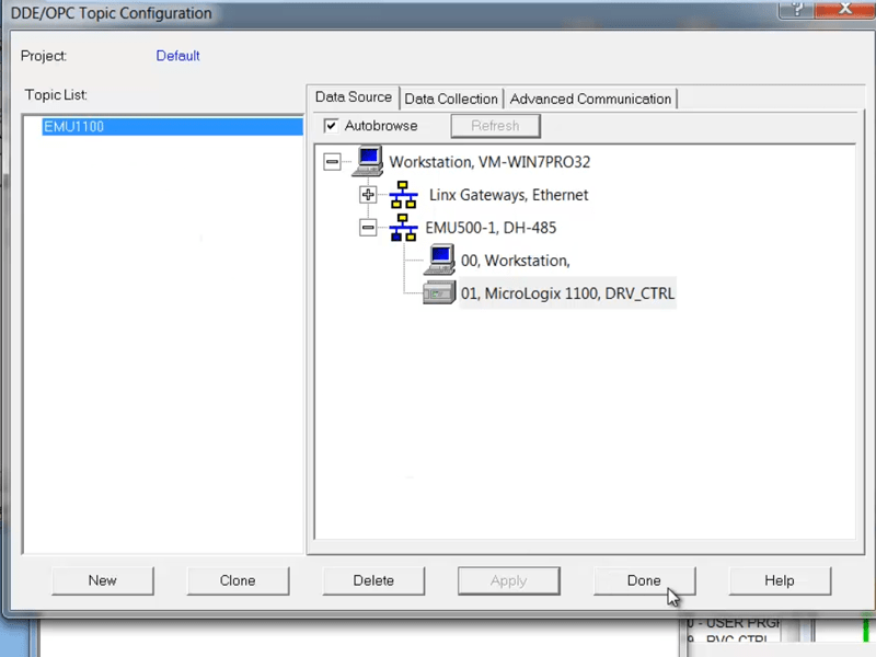
Step 6) And select “Yes” to update your Topic:
Step 7) Now that we’re done setting up our new “Topic,” we can close the configuration window by clicking on “Done”:
NOTE: You can purchase “ad free” copies of our articles, videos, and sample code for $1 each here. Or become a “Patron” for as little as $1 a month and receive at least $3 worth of articles/videos/sample code free each month! Find out more here.
Step 8) Moving over to FactoryTalk View Studio, right click on your application in the Project Explorer and select “OPC Data Server” from the “Add New Server” menu:
Step 9) In the properties window, give your OPC Server a name. In the below example “RSLinx Classic” was used:
Step 10) Then under “OPC Server Name” select “Browse”:
Step 11) Now select “RSLinx OPC Server” from the list, and click on “OK”:
Step 12) Then select “Apply” and “Close”:
Step 13) Now to see the tags available in your emulated PLC, you may need to right click in the Tag Browser and “Refresh All Folders” as shown below:
NOTE: One setting that could cause your tags not to appear would be if RSLinx Enterprise had “Shortcuts” with the same names as RSLinx Classic “Topics.” For example, if we had an RSLinx Enterprise “Shortcut” named “EMU1100,” we may not be able to browse for tags from our RSLinx Classic “Topic” of the same name.
Step 14) Once the folders refresh, you should see the available PLC addresses in your emulated PLC:
NOTE: Using RSLinx Classic and RSEmulate to test your graphics and animations can be very helpful. However, while this works on a PC, it will not work on the PanelView Plus as has neither RSLinx Classic or RSEmulate onboard.
If you’d like to watch a video demonstration of the above, check out Episode 4 of The Automation Minute Season 4 below:
Have a question or comment? Please feel free to ask me here.
Until next time, Peace ✌️
If you enjoy this episode please give it a Like, and consider Sharing as this is the best way for us to find new guests to come on the show.
Eliminate commercials and gain access to my weekly full length hands-on, news, and Q&A sessions by becoming a member at The Automation Blog or on YouTube. You'll also find all of my affordable PLC, HMI, and SCADA courses at TheAutomationSchool.com.
I'm a lifelong Technology Enthusiast who began programing in the early 80's on the Apple II and VIC-20 personal computers. After earning a degree in Electronics, I worked as a Certified Controls and Information Automation Specialist for 25 years before leaving to become a full time Industrial Automation instructor and mentor at TheAutomationSchool, as well as publishing industry interviews, news, and product how-to’s at TheAutomationBlog.com. If you're interested in my training, mentoring, or becoming a sponsor, please schedule a teams meeting with me via https://calendly.com/shawntierney/business-meeting
Eliminate commercials and gain access to my weekly full length hands-on, news, and Q&A sessions by becoming a member at The Automation Blog or on YouTube. You'll also find all of my affordable PLC, HMI, and SCADA courses at TheAutomationSchool.com.
I'm a lifelong Technology Enthusiast who began programing in the early 80's on the Apple II and VIC-20 personal computers. After earning a degree in Electronics, I worked as a Certified Controls and Information Automation Specialist for 25 years before leaving to become a full time Industrial Automation instructor and mentor at TheAutomationSchool, as well as publishing industry interviews, news, and product how-to’s at TheAutomationBlog.com. If you're interested in my training, mentoring, or becoming a sponsor, please schedule a teams meeting with me via https://calendly.com/shawntierney/business-meeting
In today’s article I cover how to scale a value in a numeric display within FactoryTalk View Studio.
A reader recently reached out to me with a problem he was having.
He had a number like 411 that he wanted to be displayed as 4.11.
But when he changed the number of digits and decimal places in the numeric display’s properties as shown below…
He found that while the display changed, the value didn’t.
So I explained to him that while those settings wouldn’t actually change the value displayed, he did have a few options to make the change he wanted.
First, I recommended he scale the value in the PLC.
That’s my preference because I’ve found it can be very helpful to have both the raw and scaled values in the PLC when you’re troubleshooting code.
But editing existing PLC code isn’t always an option, so I also mentioned he could easily scale the Tag’s value in the Tag’s settings IF his numeric display referenced an HMI Tag .
However, when using Logix base processors most designers directly reference tags in the controller, and therefore I told him the easiest option would likely be to scale the value right there in the numeric display itself.
And that can be done by following the five simple steps below:
NOTE: You can purchase “ad free” copies of our articles, videos, and sample code for $1 each here. Or become a “Patron” for as little as $1 a month and receive at least $3 worth of articles/videos/sample code free each month! Find out more here.
Step 1) With the graphic open in View Studio, double click on the numeric display in question:
Step 2) Then select the “Connections” tab:
Step 3) Then click on the “Exprn” button to open the expression editor:
Step 4) Then enter in your expression and click on “OK” and then save your graphic display.
Note: In this example I divide the Tag by 100:
Step 5) Now when you test the display (or run the project) you’ll see the actually value displayed is not the tag value but instead the result of your numeric display’s expression:
Watch me demonstrate this procedure below in Episode 3 of The Automation Minute Season 4:
Have a question or comment? Please feel free to leave them with us HERE.
Until next time, Peace ✌️
If you enjoy this episode please give it a Like, and consider Sharing as this is the best way for us to find new guests to come on the show.
Eliminate commercials and gain access to my weekly full length hands-on, news, and Q&A sessions by becoming a member at The Automation Blog or on YouTube. You'll also find all of my affordable PLC, HMI, and SCADA courses at TheAutomationSchool.com.
I'm a lifelong Technology Enthusiast who began programing in the early 80's on the Apple II and VIC-20 personal computers. After earning a degree in Electronics, I worked as a Certified Controls and Information Automation Specialist for 25 years before leaving to become a full time Industrial Automation instructor and mentor at TheAutomationSchool, as well as publishing industry interviews, news, and product how-to’s at TheAutomationBlog.com. If you're interested in my training, mentoring, or becoming a sponsor, please schedule a teams meeting with me via https://calendly.com/shawntierney/business-meeting
Eliminate commercials and gain access to my weekly full length hands-on, news, and Q&A sessions by becoming a member at The Automation Blog or on YouTube. You'll also find all of my affordable PLC, HMI, and SCADA courses at TheAutomationSchool.com.
I'm a lifelong Technology Enthusiast who began programing in the early 80's on the Apple II and VIC-20 personal computers. After earning a degree in Electronics, I worked as a Certified Controls and Information Automation Specialist for 25 years before leaving to become a full time Industrial Automation instructor and mentor at TheAutomationSchool, as well as publishing industry interviews, news, and product how-to’s at TheAutomationBlog.com. If you're interested in my training, mentoring, or becoming a sponsor, please schedule a teams meeting with me via https://calendly.com/shawntierney/business-meeting
Recently a reader posted on The Automation Forums asking how he could set or change the I/O base selected in his RSLogix Micro program.
Since it’s not completely straight forward, I thought I’d post a short article with screenshots showing how to make this change.
Step 1) Open your MicroLogix program in RSLogix Micro Starter, Micro, or 500. Then from the Project tree on the left, expand the Controller folder and double-click on ‘”IO Configuration”:
Step 2) Next, in the IO Configuration window double click on the MicroLogix Base in “Slot #0”:
Step 3) Here 0n the default “Embedded General Configuration” tab, select the base that matches the hardware you have and click on “OK”:
Step 4) Now close the IO Configuration window, save your project, and when you’re ready download it to your MicroLogix.
Watch me demonstrate the above procedure live in Episode 2 of The Automation Minute Season 4:
Have a question or comment on the above? Please feel free to leave them with us HERE.
Until next time, Peace ✌️
If you enjoy this episode please give it a Like, and consider Sharing as this is the best way for us to find new guests to come on the show.
Eliminate commercials and gain access to my weekly full length hands-on, news, and Q&A sessions by becoming a member at The Automation Blog or on YouTube. You'll also find all of my affordable PLC, HMI, and SCADA courses at TheAutomationSchool.com.
I'm a lifelong Technology Enthusiast who began programing in the early 80's on the Apple II and VIC-20 personal computers. After earning a degree in Electronics, I worked as a Certified Controls and Information Automation Specialist for 25 years before leaving to become a full time Industrial Automation instructor and mentor at TheAutomationSchool, as well as publishing industry interviews, news, and product how-to’s at TheAutomationBlog.com. If you're interested in my training, mentoring, or becoming a sponsor, please schedule a teams meeting with me via https://calendly.com/shawntierney/business-meeting


You must be logged in to post a comment.