Home Blog Page 46

Designing and Specifying for Industrial Automation, Part 1

Let’s talk about something that is not only a large portion of any controls engineer’s duties but is one of the most important aspects of my career…specifying the components for your automation project.  In the order of joy in my work, this is second-place only to the fun of bringing it all to life with some code and a little power.

The power-up and commissioning is, of course, my favorite part and can be very rewarding if the design is done correctly upfront.  With that said, this will be a two-part overview of what steps I take on a general design as I get started so that the commissioning goes as smoothly as possible.

These steps, of course, can vary depending on the scope as well as the engineer’s approach.  This is meant to only give a basic idea of an approach that has worked for me for 25 years.

Here is a quick list of what I would consider my main steps.

  1. Concept (Scope) – Part One
  2. General components – Part One
  3. Panel size – Part One
  4. Layout – Part One
  5. Design Detail/Schematics Generation Part Two
  6. Connectivity and Additional components added Part Two
  7. BOM Part Two

Concept:

This is where the general operation of the machine or system and scope of the project is evaluated.  After the scope is established, typically I will take any similar designs (from projects that are recently done or some that are recent enough to still be remembered by myself or teammates) into consideration as a template or as a good starting point before proceeding.  This has the potential to greatly reduce any “cradle to grave” time for the design and commissioning.  If all the differences between the new project and template are simple, like some sizing of motors, you can quickly update a few overload protection components and BOM line items to get the project kicked off in the right direction.

General Components:

I consider the general components to be the enclosure(s) (used to set back panel sizing), PLC and HMI selection, and any other major panel components such as drives, contactors, servos, transformers (if mounted on the back panel or enclosure), estimated fusing holder count (finalized amperage sizing and count in Design Detail), and any relays (simple safety, programmable safety, and terminal or ice-cube relays).

Panel Size:

Here is where having an example or a template helps cut the most time.  This is the step where I want to work closely with the mechanical designer or system designer so I can be sure to know if there is more clearance or restricted dimensions in either the vertical or horizontal direction. This will give me an initial idea of the orientation of the cabinet.

Industrial Enclosure Photo by Mika Baumeister on Unsplash

I will also want to know what clearances there are around the enclosure to narrow down to a single or multiple-door enclosure.  Otherwise, in the cad package (I have always used AutoCAD) I just start putting the one-to-one scaled drawings of the components side-by-side and in an arrangement that also ensures separation of the higher voltage (240 Vac or 480 Vac) items and the control voltage (typically 24 Vdc these days).

Once roughed in, I may draw a rectangle around the parts and measure with some dimensions to get a rough idea so I can narrow it down to the size of the back panel.  I will typically grab a commonly used or standard back panel drawing and use it instead of the rectangle approach.

Don’t forget the importance of any needed space for wire trough or cable management.  Another important detail here is the clearances you need to consider around any drives, disconnects, or other higher wattage loss items that may generate heat.

Once you get here, you can narrow it down to a standard size from your preferred vendor or stocked items.  I do find that, although rare, a custom enclosure may be the best option.

Panel Layout:

The keys to a successful panel layout are accurate 1:1 drawings of the panel, components, and being sure you have the right dimensions for any wire trough you use.  From day one in my career, I learned that a component drawing used on the panel that did not include the same dimensions as the purchased part, meant a real headache for the assembly personnel as they tried to get everything to fit.

Possibly even the purchase of a new panel to accommodate the difference.  At this OEM, a specific wire trough used had always been drawn to size.  This did not include the dimensions of the wire tray cover.  This small amount built up to quite a distance when used over a larger panel.

I will also use the dimensions for the location of the disconnect location first and lay the other components around that fixed position.  This step is important to remember the location of the through-the-door operation handle.  Getting those dimensions relative to the location of the panel should most likely be the first step in the panel layout.

I hope you found this first part of my two part series helpful! In the next part I’ll get into the finer details of the Schematic Design and BOM.

Written by Paul Hunt
Senior Automation Engineer and Freelance Writer

Have a question? Join our community of pros to take part in the discussion! You'll also find all of our automation courses at TheAutomationSchool.com.

Sponsor and Advertise: Get your product or service in front of our 75K followers while also supporting independent automation journalism by sponsoring or advertising with us! Learn more in our Media Guide here, or contact us using this form.

Paul Hunt
 

First Look: SEL1400 Selectivity Module from Siemens (M5E18)

We take a first look at the SEL1400 Selectivity Module from Siemens in this episode of The Automation Minute.


The Automation Minute, Season 5 Episode 18 Show Notes:

Special thanks to Siemens for sending us a sample of their SEL1400 selectivity module!


Join our new community at TheAutomationBlog.com/join!

Become part of our community to take part in the Q&A as well as get early access to many of our Podcasts and Shows with a one-time or monthly pledge of $5

Vendors: Would you like your product featured on the Podcast, Show or Blog? If you would, please contact me at: https://theautomationblog.com/contact

Until next time, Peace ✌️ 

If you enjoy this episode please give it a Like, and consider Sharing as this is the best way for us to find new guests to come on the show.

Shawn M Tierney
Technology Enthusiast & Content Creator

Eliminate commercials and gain access to my weekly full length hands-on, news, and Q&A sessions by becoming a member at The Automation Blog or on YouTube. You'll also find all of my affordable PLC, HMI, and SCADA courses at TheAutomationSchool.com.

Paul Hunt

Community Q & A: Questions of the Week

This week a lot of readers made use of our updated “submit a question” link to send us topics they’d like to see us cover, and today I’ll share a few of them along with thoughts on how to resolve each.

Note: Readers can ask me questions directly at TheAutomationBlog.com/join, or submit them for consideration for coverage on the blog here.


Question:

I have a MICRO850 PLC and a PANELVIEW 7 STANDARD 10.4″. The problem is that when you download the program in the HMI, the message “the item is no longer available” appears and the values of any tag are not displayed.

However, when I simulate the screens on my PC and the MICRO850 PLC is in RUN if the values of all the tags are displayed.

So, is it possible for Micro850 to communicate with a PanelView Plus 7?

Shawn’s Take:

Rockwell typically does a good job walking users through how to connect their HMI’s to their PLCs, and in the case of the PanelView Plus and Micro850 they’ve published quite a few tech notes on this topic, we I even covered it in an article here.

If you’d like to see the Rockwell Tech Notes, head over to http://www.AB.com, then click on Knowledgebase, and search on “PanelView Plus Micro850.”

The first one I’d recommend reading is IN2129 – PanelView Plus 7 Communications to Allen-Bradley Controllers


Question:

CCW for the Micro810 PLC, what is feature password? It might be a problem with my windows, but how to fix it?

Shawn’s Take:

The use of passwords in PLCs and Programming Software is a complicated subject, and honestly your question is very vague.

I suggest checking out two excellent documents which explain passwords in this PLC line in detail, which you’ll find here and here.

Then if you still have questions on a specific password feature, you’re welcome to submit it for us to consider covering in a future article.


Question:

We’ve used the Allen-Bradley E3 Plus Devicenet models for awhile, and now have added the E300 Devicenet electronic relays.

Problem is, I can’t find any “add-on profiles” on the Rockwell website for the Devicenet units though. Am I looking in the wrong place?

Shawn’s Take:

While we don’t have any E300 units in our inventory, I did just fire up Studio 5000 version 30 and found that the E300 was listed there as an item I could add to my Ethernet module.

I then searched the Rockwell Knowledgebase, and found an article with a direct link to AOPs (here) which listed several different AOPs for the E300.

With that in mind, I’d recommend trying to use the AOP for the E300 that’s already in Studio 5000 if possible, but if it doesn’t support your device, check out the list I linked to above.


Question:

Is there any tool or method to migrate a scada win cc from siemens to factorytalk view SE?

Shawn’s Take:

Rockwell includes migration tools in their software to migrate from old versions of their products to new versions (like from the PanelView Standard to PanelView Plus, as well as from the SLC-500 to ControlLogix.)

And in the past they have also used internal tools to help customers to migrate projects from competitor’s HMIs and SCADA to their own. But to learn if Rockwell can help you with your specific request you’ll need to reach out to your local Rockwell representative.


If you’d like to see our previous Q & A’s, click here. And to submit a question for us to consider covering in a future blog, click here. And those readers who’d like to ask me questions directly, can do so here.

Until next time, Peace ✌️ 

If you enjoy this episode please give it a Like, and consider Sharing as this is the best way for us to find new guests to come on the show.

Shawn M Tierney
Technology Enthusiast & Content Creator

Eliminate commercials and gain access to my weekly full length hands-on, news, and Q&A sessions by becoming a member at The Automation Blog or on YouTube. You'll also find all of my affordable PLC, HMI, and SCADA courses at TheAutomationSchool.com.

Paul Hunt

TIA Portal – v17: View of Things – Graphics and Dashboards Made Easy (D007)

Learn how to quickly create dashboards and download them to a S7-1500 using TIA Portal v17 and new View of Things feature in Episode 7 of The Automation Demo (originally episode 3 of Automation Tech Tips.)

For more information, check out the “Show Notes” located below the video.


The Automation Demo Episode 7 Show Notes (originally Tech Tips Episode 3:)

A huge thank you to Luis from Siemens for coming on Automation Tech Tips!


If you’re a vendor who’d like your product featured on our site or show, please contact us at: https://theautomationblog.com/guest

Until next time, Peace ✌️ 

If you enjoy this episode please give it a Like, and consider Sharing as this is the best way for us to find new guests to come on the show.

Shawn M Tierney
Technology Enthusiast & Content Creator

Eliminate commercials and gain access to my weekly full length hands-on, news, and Q&A sessions by becoming a member at The Automation Blog or on YouTube. You'll also find all of my affordable PLC, HMI, and SCADA courses at TheAutomationSchool.com.

Paul Hunt

PanelView 800 – Datalogging and Trending

In today’s article I’ll walk you through how to setup Data Logging and Treading in CCW, covering the basic setup and provide an example as to the capabilities of each.

PanelView 800 Family

Trends in CCW

I had worked with CCW for weeks without ever really noticing the “Trends” button at the top of the project organizer. Kind of a “can’t see the forest for the trees” kind of thing I guess, but it is right there next to “Devices”, in which I now have a PanelView 800, Micro 820 and a Powerflex 525 in my project.

Adding a Trend to the Project

Select the trend add or delete buttons shown below to add a trend to the project or remove a trend from the project.

To see the trend properties, look for this button on the right side of the trend window.

Adding Traces to the Project

Traces are the “pens” or tags that you wish to log in the trend. Click the + sign under the Traces header to begin adding Traces to the Trend.

A popup window opens and as you can see here, I have the option to browse to my Powerflex Drive or my Micro820 controller to pick from available tags to trend.

I chose to browse to the Micro820 Controller tags and select two tags from my PID controller that I created in an earlier article. Select “Add” and “Ok” to finish adding the tags.

Click on the trace to see and set the properties for a trace, as shown below.

“Sampling” & “Trigger” Properties

Under the sampling tab, you can set the sampling rate for the traces and time frame of the trend window as well as trend capture size.

Here, for the sake of testing, I set it to two minutes, so I don’t have a huge amount of data to collect. The “Trigger” of the trend can be manual, an analog value, single bit or a time to start the trend.

Trend Operation

To start/stop the trend, in manual, select the icon in the upper left corner of the trend to start or stop.

Data Logging and Capture

Trend data can be captured and exported to a CSV file or sent to a print file as shown below. Click the “Export to CSV” button to export trend data to excel.

Give the CSV file a name and click “save”

Open the CSV file in Excel to view data.

Conclusion

While there are many settings, properties, and configuration options to setting up a trend in CCW, it is straightforward and easy to implement.

While it looks different, it is certainly akin to trending in Studio 5000. It can definitely be a tool to use in setting up, tuning or troubleshooting a system. I hope this helps you at least know the feature is available in CCW and how to implement it.

Written by Brandon Cooper
Senior Controls Engineer and Freelance Writer

Have a question? Join our community of pros to take part in the discussion! You'll also find all of our automation courses at TheAutomationSchool.com.

Sponsor and Advertise: Get your product or service in front of our 75K followers while also supporting independent automation journalism by sponsoring or advertising with us! Learn more in our Media Guide here, or contact us using this form.

Paul Hunt
 

First Look: RVP510 Encoder with Display from IFM (M5E17)

We take a first look at the RVP510 Encoder with Display from IFM in this episode of The Automation Minute.


The Automation Minute, Season 5 Episode 17 Show Notes:

Special thanks to IFM for sending us a sample of their RVP510 Encoder with Display!


Join our new community at TheAutomationBlog.com/join!

Become part of our community to take part in the Q&A as well as get early access to many of our Podcasts and Shows with a one-time or monthly pledge of $5

Vendors: Would you like your product featured on the Podcast, Show or Blog? If you would, please contact me at: https://theautomationblog.com/contact

Until next time, Peace ✌️ 

If you enjoy this episode please give it a Like, and consider Sharing as this is the best way for us to find new guests to come on the show.

Shawn M Tierney
Technology Enthusiast & Content Creator

Eliminate commercials and gain access to my weekly full length hands-on, news, and Q&A sessions by becoming a member at The Automation Blog or on YouTube. You'll also find all of my affordable PLC, HMI, and SCADA courses at TheAutomationSchool.com.

Paul Hunt

View Designer – New Features Planned for v8

I recently sat down with Keith Hogan, product manager for View Designer and PanelView 5000 HMIs, to learn more about his products and new features planned for the next release of the software.

In today’s article I’ll share the highlights of what I learned, and if you’d like to watch (or listen) to my complete podcast with Keith you’ll find it here.

Image courtesy of Rockwell Automation’s appearance on The Automation Podcast Ep. 74

Let’s start with the new features common to both the 5310 and 5510 HMIs.

The first on the list is the ability to choose where on the screen the popup keypad is displayed by choose one of nine choices.

Image courtesy of Rockwell Automation’s appearance on The Automation Podcast Ep. 74

This is very helpful when you still need to see the information below the keypad, and also helps when you have multiple numeric inputs spread across your display.

Next is the ability to clear a specific data log. Unlike like previous PanelView products, the PV5000 supports up to three datalogs running at a time, for a total of 1.296 billion data points across all log files.

Third on my list is support for the new Automatic Diagnostics feature which was added into Logix Designer in version 33.

This allows PanelView 5310 and 5510 HMIs to automatically show control system faults without any configuration on the HMI side.

Image courtesy of Rockwell Automation’s appearance on The Automation Podcast Ep. 74

These new faults appear on a new system banned indicator (Heart shape) which upon pressing the user will be brought to a pre-defined Automation Diagnostics Screen.

Also new are the Automatic Diagnostics Summary and History Elements added to support this new feature.

View Designer itself also has been improved in v8.

Saving projects is up to two times faster, projects load up to four times faster, and Find/Replace operations are up to 32 times faster.

Runtimea have also seen speed increases, with screen switching speed now occurring up to twice as fast, and downloads completing up to 25 time faster.

In additional to those improvements, the PanelView 5510 is also getting some additional enhancements.

One is the increase support for a total of 500 Screens and Popups (The 5310’s limit stays at 100.)

But probably the biggest new feature for the 5510 in v8 is the new Web Browser support.

The new HTML5 browser supports Web Pages, MP4 Videos, and even IP Cameras using H.264 or MJPEG.

Image courtesy of Rockwell Automation’s appearance on The Automation Podcast Ep. 74

It’s configurable in size, look and feel, including position and menu bar settings.

The browser supports content on the internet or a private intranet, as well as on the USB and SD locations. It also supports the built-in web pages found in many Rockwell products.

And those are the highlights of what’s planned for version 8 of View Designer.

As with any early look at a future release of software, there’s always a chance the software’s release will be postponed, or that the features mentioned will be delayed or changed.

If you’d like to know more about the PanelView 5000 line and View Designer, check out all our previous coverage here.

Until next time, Peace ✌️ 

If you enjoy this episode please give it a Like, and consider Sharing as this is the best way for us to find new guests to come on the show.

Shawn M Tierney
Technology Enthusiast & Content Creator

Eliminate commercials and gain access to my weekly full length hands-on, news, and Q&A sessions by becoming a member at The Automation Blog or on YouTube. You'll also find all of my affordable PLC, HMI, and SCADA courses at TheAutomationSchool.com.

Paul Hunt

View Designer and PanelView 5000 Update with Rockwell Automation (P74)

In this episode of The Automation Podcast, I sit down with Keith Hogan of Rockwell Automation to learn what’s new and coming for the PanelView 5000 line of HMIs and Studio 5000 View Designer software.

Note: As this episode was not sponsored by the vendor, the video edition is only available to our members here on The Automation Blog and on YouTube. For more information, check out the “Show Notes” located below the video.


Watch to the Podcast on The Automation Blog:


Note: As mentioned above, this episode was not sponsored by the vendor so the video edition is a “member only” perk. The below audio edition (also available on major podcasting platforms) is available to the public and supported by ads. To learn more about our membership/supporter options and benefits, click here.


Listen to the Podcast:


The Automation Podcast, Episode 74 Show Notes:

Special thanks to our members for making this show possible! To learn more about becoming a member, click here.


Vendors: Would you like your product featured on the Podcast, Show or Blog? If you would, please contact me at: https://theautomationblog.com/contact

Until next time, Peace ✌️ 

If you enjoy this episode please give it a Like, and consider Sharing as this is the best way for us to find new guests to come on the show.

Shawn M Tierney
Technology Enthusiast & Content Creator

Eliminate commercials and gain access to my weekly full length hands-on, news, and Q&A sessions by becoming a member at The Automation Blog or on YouTube. You'll also find all of my affordable PLC, HMI, and SCADA courses at TheAutomationSchool.com.

Paul Hunt

PanelView 800 – Using the Recipe Feature

Today I walk through creating and using recipes in the PanelView 800 using Connected Components Workbench. In this example my Panelview 800 touchscreen connected to a Micro820 controller.

Note that I have never used the PV800 recipe feature before, so I’m curious how easy it is to implement, and how I could use its capabilities in the future.

PanelView 800 10 Inch

In a past job, over a decade ago, I was involved in making composite panels for a living, so for my test project today, I will make a memorial composite panel recipe, or at least a small part of one, to test out creating recipes in my PV800 terminal.

PLC Tags and Program in the Micro820 Controller

The PLC only needs tags or an array to download the recipe to. Here, I created five tags in an array called “RECIPE[]”.

Only for example, I created a program routine called “Recipe_Program” to use “MOV” instructions to move the RECIPE array to other tags.

In my composite panel recipe array in the Micro820 controller, I now have tags for Resin, Urea, Scavenger, Water and Line Speed.

This is all I really need to create recipes to load to these variables from my PV800. I downloaded these changes to the Micro820 and it is in run mode.

PV800 Recipe Configuration and Graphics

In the PV800 project, I must first add the tags for my recipe in the tag database as shown below.

In the “Recipes” section, I now need to create my recipes. I created one recipe for “HEAVY” panels and another recipe for “LIGHT” panels.

Here I can connect Recipe names with the Tags that I previously created in the global tag database.

Now for the most difficult part. The graphics were not easy. I created a screen called “Recipe”. There is no total recipe handling window, but many objects that need to be used together to select, load, modify, etc.. the recipes. As shown below, I added the recipe objects from the advanced toolbox: Recipe Download Button, Recipe Restore Button, Recipe Save Button, Recipe Upload Button, Recipe Selector Object and the Recipe Table Object.

I also needed to add “Key” objects to create the up/down buttons for both the selector and the table, as well as, “enter” buttons for the recipe selector and the recipe table. Use the “Link target” parameter in these buttons to connect to the appropriate object by the object name.

Recipe Table object properties.

Recipe Selector object properties.

I then validated and downloaded the project to the PV800 terminal.

Runtime

I used the recipe selector’s up/down buttons to select the desired recipe, and then click the “enter” button for the recipe selector.

Next I click of the “Restore” button to populate the recipe to the recipe table.

To edit the recipe, I use the recipe table’s up/down buttons to select the ingredient I want to modify, and then after editing the value I click the “Save” button to save the recipe.

To download the recipe, you simple select the “Download” button to download to current recipe to the Micro820 controller.

IF you’d like to upload the recipe from the Micro820, you simply select the “Upload” button.

Here the “LIGHT” recipe is selected and downloaded.

 Conclusion

As far as basic setup in the Micro820 and PV800, configuring recipes is very simple.

I’ll be honest, as far as the graphics are concerned, this was difficult. It took me nearly two hours to figure out how to configure all the buttons, selectors, colors and make the graphic look like I wanted to and work as desired.

I found some online pieces of resources, but nothing that completely took me through this process and the help files in CCW have a lot to be desired. Creating recipes in CCW, because of the graphics, will certainly give any experienced HMI engineer an IQ test that they must pass.

I hope this article helps you with your recipe creating and handling in a CCW project.

Written by Brandon Cooper
Senior Controls Engineer and Freelance Writer

Have a question? Join our community of pros to take part in the discussion! You'll also find all of our automation courses at TheAutomationSchool.com.

Sponsor and Advertise: Get your product or service in front of our 75K followers while also supporting independent automation journalism by sponsoring or advertising with us! Learn more in our Media Guide here, or contact us using this form.

Paul Hunt
 

First Look: GS21 HMI from Mitsubishi (M5E16)

We take a first look at the GS21 HMI from Mitsubishi in this episode of The Automation Minute.


The Automation Minute, Season 5 Episode 16 Show Notes:

Special thanks to Mitsubishi for sending us a sample of their GS21 HMI!


Join our new community at TheAutomationBlog.com/join!

Become part of our community to take part in the Q&A as well as get early access to many of our Podcasts and Shows with a one-time or monthly pledge of $5

Vendors: Would you like your product featured on the Podcast, Show or Blog? If you would, please contact me at: https://theautomationblog.com/contact

Until next time, Peace ✌️ 

If you enjoy this episode please give it a Like, and consider Sharing as this is the best way for us to find new guests to come on the show.

Shawn M Tierney
Technology Enthusiast & Content Creator

Eliminate commercials and gain access to my weekly full length hands-on, news, and Q&A sessions by becoming a member at The Automation Blog or on YouTube. You'll also find all of my affordable PLC, HMI, and SCADA courses at TheAutomationSchool.com.

Paul Hunt

Studio Wall Parts Detailed (What’s New At The Automation School)

In this video I bring students up to speed on the remodeling my studio, including the reason for the additional of products on the product wall, as well as the process I used to pick out the plastic panels for the modular training system I’m using.

For all the links mentioned, check out the “Show Notes” located below the video.


Show Notes for What’s New In School, Episode 07-30-21:

Link to Wall Control (Amazon):

Link to 1×2 plastic sheets (Amazon):
(2024 Update – the options on Amazon have narrowed over the last few years.)

Link to alternate seller of plastic sheets:
(2024 Update – I’ve started using BuyPlastic.com as they have better pricing)

Link to contact Shawn about anything school related:

Until next time, Peace ✌️ 

If you enjoy this episode please give it a Like, and consider Sharing as this is the best way for us to find new guests to come on the show.

Shawn M Tierney
Technology Enthusiast & Content Creator

Eliminate commercials and gain access to my weekly full length hands-on, news, and Q&A sessions by becoming a member at The Automation Blog or on YouTube. You'll also find all of my affordable PLC, HMI, and SCADA courses at TheAutomationSchool.com.

Paul Hunt

Studio / RSLogix 5000 – Can’t Go Online (Q&A)

In this edition of “Community Q & A,” one of our locals community members needs help connecting to his ControlLogix Controller.

Note: To see a list of all our ControlLogix videos and articles, click HERE.

Community Question:

I have an A-B ControlLogix controller that I tried to go online with using Ethernet and USB but it failed.

When connecting via Ethernet all other modules appear with cross on them, but when connecting via USB every module is shown without any crosses?

The PLC OK led is flashing red (which is major recoverable error as I understand), the PLC have backup memory but however recycling the power does not clear the fault. The ControlNet module (1756-CNBR/E) has a red flashing light on the B PNC port, but I don’t know if that’s causing the issue?

The Controller is a 1756-L62 and RSLogix 5000 is v19.1, which should be the same as the version on the PLC. The Ethernet address is 172.16.0.100, and I changed my PC IP to 172.16.0.xxx, were I make sure xxx and not being used by any device on the network.

Shawn’s Reply:

Good morning,

Let’s see if I can help you walk through this step by step.

Ethernet Communications

First, to connect your PC to the Controller over Ethernet the subnet masks should match – you didn’t share your subnet masks, so I’ll assume that setting in your PLC and your PC match.

Next, after connecting both devices to an Ethernet switch (to avoid any auto-mdix issues,) you should attempt to ping the PLC in a Command Prompt Window to insure your PC and PLC can communicate to prove they are on the same logical network and there are no physical network issues. For more info on this see How To Ping a PLC.

Once you can Ping the PLC, if it still doesn’t show up under the Ethernet/IP driver, check that driver’s setup to be sure you selected your Physical Ethernet Card in your PC, the one with the similar address as the PLC (and not the Wifi or Blue-tooth networks.)

If your PLC still doesn’t show up under the Ethernet/IP driver, try the Ethernet Devices Driver and in it’s configuration add your PLC’s Ethernet Address to the list, and then see if it shows up without a Red X in the RSWho window.

USB Communications

When using RSLinx USB communications, it sometimes won’t work IF the Virtual Backplane driver is already present in RSLinx prior to plugging your USB cable into your device.

So to avoid this USB / RSLinx issue, make sure to manually delete the VBP driver from RSLinx (if it’s present) prior to plugging your PC into the USB port of the A-B device.

And on the off chance you can’t get the Ethernet or USB drivers working, you can always try the controller’s Serial Port as well.

Faulted Controller

Once connected to the controller via Ethernet or USB, you should be able to view any errors in the PLC, or if the PLC program is not present then you should be able to load the program.

I’ve found most of the time I run into a flashing Red light fault light on an A-B PLC that it typically means that the Controller has lost it program due to a power spike, which happens often when there are severe thunderstorms in the area.

Since this L6x controller should have a CompactFlash card slot for use with CF cards (that operate as Non-Volatile memory,) hopefully the last person to change the program has loaded the latest version of that program unto the CF card installed in the controller.

Often times people will remember to load the program onto the card, but forgot to set it to auto-load on corrupt memory. If that’s the case, someone will have to connect to the controller to load the program from the card manually (I’ve seen this quite a bit.)

ControlNet Module

Before getting to your question, I first want to point out that the RJ45 port on ControlNet modules is NOT an Ethernet port. It’s actually a ControlNet “Network Access Port” (NAP) and requires a special ControlNet communications card to use.

As far as the ControlNet module, I wouldn’t concern yourself with the B channel unless it is being used AND all devices are connected.

If it is wired to all the other devices on the network I don’t believe it should be flashing Red, however we should really wait until you’ve connected to the PLC and eliminated the fault before troubleshooting your ControlNet redundant network.

Hope this helps – please let us know what you find,


If you have a question you’d like me to answer, please don’t hesitate to post it at https:// TheAutomationBlog.com/join. Or if it’s just something you’d like to see me cover in a future piece, you can submit it to me here at https://theautomationblog.com/questions/.

To learn more about the ControlLogix, including Ethernet, ControlNet, Serial, and DH+ communications, Firmware loading, Programming, PlantPAx and VFD integration, check out my ControlLogix Course Here.

For a limited time students who enroll in the above course will also get my upcoming ControlLogix course, Ultimate Logix™ free of charge!

Until next time, Peace ✌️ 

If you enjoy this episode please give it a Like, and consider Sharing as this is the best way for us to find new guests to come on the show.

Shawn M Tierney
Technology Enthusiast & Content Creator

Eliminate commercials and gain access to my weekly full length hands-on, news, and Q&A sessions by becoming a member at The Automation Blog or on YouTube. You'll also find all of my affordable PLC, HMI, and SCADA courses at TheAutomationSchool.com.

Paul Hunt

Import Festo CPX-AP-I into Logix and Studio 5000 (D006)

Learn how to quickly and easily import a Festo CPX-AP-I system directly into Logix and Studio 5000 in Episode 6 of The Automation Demo (originally episode 2 of Automation Tech Tips.)

For more information, check out the “Show Notes” located below the video.


The Automation Demo Episode 6 Show Notes (originally Tech Tips Episode 2:)

A huge thank you to Sandro from Festo and for coming on Automation Tech Tips!


If you’re a vendor who’d like your product featured on our site or show, please contact us at: https://theautomationblog.com/guest

Until next time, Peace ✌️ 

If you enjoy this episode please give it a Like, and consider Sharing as this is the best way for us to find new guests to come on the show.

Shawn M Tierney
Technology Enthusiast & Content Creator

Eliminate commercials and gain access to my weekly full length hands-on, news, and Q&A sessions by becoming a member at The Automation Blog or on YouTube. You'll also find all of my affordable PLC, HMI, and SCADA courses at TheAutomationSchool.com.

Paul Hunt

SIMATIC HMI Basic Panel – Using the Recipe Feature

Whether we are manufacturing beverages, wood panels, chemicals, pharmaceutical or any other product in industry, one common feature they all share, is they are created with consistency by using recipes.

Every product contains a list of ingredients that needs to be precise, day after day and shift after shift, to deliver consistent products to customers every single day.

Today I’ll walk through creating a recipe for a Siemens Basic Panel HMI in TIA Portal  to be used with a Siemens S7-1200.

In my example I’m going to have a little fun and recipes of life’s priorities – one for a balanced life and another for an overworked life.

PLC Setup – S7-1200 programming

The first thing I did was to add a data block to my S7-1200 with tags for each of my recipe ingredients. Ingredients are all “REAL” data type and are designed to be entered in minutes of a day spent on each task.

My next task was to add a simple (cyclic interrupt) ladder program for my recipe. Here I add all the ingredients together except for one.

I then subtract all the ingredients that were added together from the total minutes in a day (1440) and I am left with the last ingredient, “SLEEP”

HMI Setup – Basic Panel HMI Project Configuration

I can now switch over and configure the HMI portion of the project. The first thing I did was to create a graphic screen called “Recipe Load”.

The next thing I did is to create a recipe, which I call “Recipe_Test”.  My recipe (shown below) contains all the elements that are in the recipe connected to the corresponding “Tag” in the plc.

On my graphic screen, I need to add a “Recipe view” which is located in the “Controls” toolbox on the right side of the TIA Portal pane. I had to do zero configuration to this Recipe view tool, simply add it to the display.

Next, I added the tags from my S7-1200 data block. This will be the “Loaded” tags in my program. The tag shown here is “PROD_RECIPE_EAT” which is the loaded recipe time spent eating each day.

I then compile and download my project. Again, the HMI simulation tool is wonderful to use here, to test and get the project correct, before downloading to the Basic HMI Panel. This saves a lot of time.

Runtime

At runtime, I can now create New Data Records of my Recipe. Simply select the Recipe and then use the four buttons in the bottom left corner of the Recipe view to: Create a New Data Record, Save the Data Record, Delete the Data Record or Rename the Data Record. In this display, I created a Data Record called “Balanced” and scrolled through each of my recipe elements and added values for how much time to spend on each element (ingredient).

Note the two buttons on the bottom right of the Recipe view – they are to download to the PLC and Upload from the PLC. Here, I have downloaded my “Balanced” data record to the PLC. This life recipe gives time to multiple aspects of an individual’s life and provides a good nights’ rest at the end of the day.

Here, I have created Data Record #2 and called it “Overworked”. I scrolled through each element and modified the recipe so that the life recipe is out of balance, with too much time spent on work, not enough on self-care or family time and at the end of the day, gets little rest. I wouldn’t recommend using Data Record #2. I also downloaded this Data Record to the PLC as shown below.

Here, I take one look back at my S7-1200 PLC program with the “Balanced” data record loaded and see the calculations working.

Conclusion

I was honestly very pleased and impressed with how easy it was to configure and manipulate recipes in TIA Portal.

I hope this project helps you with your first recipe handling project in TIA portal, and I encourage you to keep the “Balanced” recipe loaded in your life instead of the “Overworked” one.

Written by Brandon Cooper
Senior Controls Engineer and Freelance Writer

Have a question? Join our community of pros to take part in the discussion! You'll also find all of our automation courses at TheAutomationSchool.com.

Sponsor and Advertise: Get your product or service in front of our 75K followers while also supporting independent automation journalism by sponsoring or advertising with us! Learn more in our Media Guide here, or contact us using this form.

Paul Hunt
 

What’s New with Siemens HMIs? (M5E15)

We take a quick look at what’s new with Siemens HMIs in this episode of The Automation Minute.


The Automation Minute, Season 5 Episode 15 Show Notes:

Check out the full session video at the Siemens Innovation’s website here.


Join our new community at TheAutomationBlog.com/join!

Become part of our community to take part in the Q&A as well as get early access to many of our Podcasts and Shows with a one-time or monthly pledge of $5

Vendors: Would you like your product featured on the Podcast, Show or Blog? If you would, please contact me at: https://theautomationblog.com/contact

Until next time, Peace ✌️ 

If you enjoy this episode please give it a Like, and consider Sharing as this is the best way for us to find new guests to come on the show.

Shawn M Tierney
Technology Enthusiast & Content Creator

Eliminate commercials and gain access to my weekly full length hands-on, news, and Q&A sessions by becoming a member at The Automation Blog or on YouTube. You'll also find all of my affordable PLC, HMI, and SCADA courses at TheAutomationSchool.com.

Paul Hunt

TIA Portal – v17: What’s New (M5E14)

We take a quick look at what’s new with Siemens PLCs in this episode of The Automation Minute.


The Automation Minute, Season 5 Episode 14 Show Notes:

Check out the full session video at the Siemens Innovation’s website here.


Join our new community at TheAutomationBlog.com/join!

Become part of our community to take part in the Q&A as well as get early access to many of our Podcasts and Shows with a one-time or monthly pledge of $5

Vendors: Would you like your product featured on the Podcast, Show or Blog? If you would, please contact me at: https://theautomationblog.com/contact

Until next time, Peace ✌️ 

If you enjoy this episode please give it a Like, and consider Sharing as this is the best way for us to find new guests to come on the show.

Shawn M Tierney
Technology Enthusiast & Content Creator

Eliminate commercials and gain access to my weekly full length hands-on, news, and Q&A sessions by becoming a member at The Automation Blog or on YouTube. You'll also find all of my affordable PLC, HMI, and SCADA courses at TheAutomationSchool.com.

Paul Hunt

Phoenix Contact WLAN Products (P73)

In this episode of The Automation Podcast, I sit down with Justin Shade of Phoenix Contact to learn about their Industrial Wireless Networking products.

For more information, check out the “Show Notes” located below the video.


Watch the Podcast:


The Automation Podcast is also available on most Video and Podcasting platforms, and direct links to each can be found here.


Listen to the Podcast:


The Automation Podcast, Episode 73 Show Notes:

Special thanks to Justin Shade of Phoenix Contact for taking the time to come on the show and give us an introduction to their line of WLAN products.


Vendors: Would you like your product featured on the Podcast, Show or Blog? If you would, please contact me at: https://theautomationblog.com/contact

Until next time, Peace ✌️ 

If you enjoy this episode please give it a Like, and consider Sharing as this is the best way for us to find new guests to come on the show.

Shawn M Tierney
Technology Enthusiast & Content Creator

Eliminate commercials and gain access to my weekly full length hands-on, news, and Q&A sessions by becoming a member at The Automation Blog or on YouTube. You'll also find all of my affordable PLC, HMI, and SCADA courses at TheAutomationSchool.com.

Paul Hunt

S7 PLCsim Advanced

While you are programming an automation application, it is sometimes useful to do some coding without the real hardware in the field, for example with a cup of fresh coffee at the warm office.

Sure, you can disassemble the machine and put the hardware on your desk. But to help you avoid doing so, TIA Portal offers two simulation possibilities.

In yesterday’s article I gave you an overview of using PLCsim, and today I’ll focus on PLCsim Advanced.

TIA Portal (picture courtesy of Siemens)

Note that in both articles I cover using them to simulate either the S7-1200 and 1500. While they also simulate the S7-300 and 400, that’s beyond the scope of these articles.

I should also note that PLCsim is available for use to anyone who has a license for TIA Portal, while PLCsim Advanced needs it’s own license which is purchased separately.

Additionally, PLCsim and PLCsim Advanced can be run simultaneously side by side on one machine, however older versions cannot be installed on the same machine at the same a time.

S7-PLCSIM advanced [V3.0]

Installation and supported devices

S7-PLCSIM advanced is also a separate installation you can also obtain from the SIOS pages here. Also S7-PLCSIM advanced will install the S7-PLCSIM V5.x to support simulation of older PLC types.

Unfortunately the S7-PLCSIM advanced does not support S7-1200 PLCs. Therefore S7-PLCSIM V16 must be installed separately. The S7-PLCSIM Advanced supports a wide range of PLCs of the 1500 series (e.g. Failsafe, Compact and technology types). Also ET 200SP types are supported like S7-1510SP. Not supported are the OpenControl (S7-1515 PC) and IPC (IndustryPC) SoftPLCs.

Editor’s note: See our TIA Portal V17 Podcast for updates on the new version of PLCsim Advanced and its support for these controllers.

Functionality

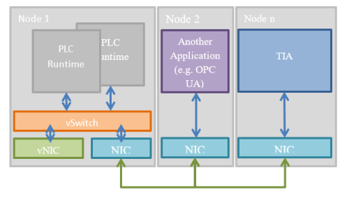
PLCSIM advanced offers mainly three different connection modes. The first one is the same as the one of PLCSIM. Here a “Softbus” will be created and the communication is done within the “Softbus”.

The second connection mode uses the “PLCSIM virtual Ethernet adapter”. That allows other applications like OPC UA clients to connect to the PLC runtimes within the same node.

The third connection mode is the “PLCSIM virtual Ethernet adapter” (vNIC) and the connection to a network interface of choice by the “PLCSIM Virtual Switch” (vSwitch). This allows also connections over network interfaces (NIC) with other nodes. Regardless if the nodes are real PCs or VMs.

HINT: Ensure the “PLCSIM virtual Switch” has a IP address from

Usage

The PLCSIM advanced UI isn’t as comprehensive as the UI of PLCSIM. This is to the fact that PLCSIM advanced has a different purpose.

The focus at PLCSIM advanced is the simulation of PLCs with interconnection to other devices and applications. Like OPC UA, S7 communication.

Also is PLCSIM advanced able to simulate features using the memory card of the plc e.g. logging.

At last but not least is PLCSIM advanced used by other tools to get PLC function into other tools like Simmit, Plant Simulate, etc.. It is also possible to create your own program using the API of PLCSIM advanced.

Create and start PLCSIM advanced PLC

First we have to select the online access PLCSIM advanced should work with. PLCSIM advanced is able to offer access like PLCSIM or over a virtual Ethernet interface.

Load PLC program into PLCSIM advanced PLC

Bevor we can load the program to the simulated PLC we have to start PLCSIM advanced. In the UI of PLCSIM advanced we select online access to “PLCSIM virtual Adapter” and TCP/IP communication with “<Local>”.

After that we have to preconfigure our target PLC instance by entering a Name, IP and Subnet Mask. By click on Start a PLC instance is created. Depending on the count of licenses we have we are able to create multiple instance of PLC (e.g. to test PLC2PLC communication).

Now we can load the PLC program into the PLCSIM advanced just like we do it with a real PLC. At the first time we load the PLC with Hardware and Software. In the “extended download dialogue” we select the PG PC interface “PLCSIM Virtual Ethernet Adapter” and start search.

After a while it will list the created instance of a plc simulation. Select the instance and load. If the PLC isn’t running you will be ask if you want to start the PLC. Click yes. Now you can see the PLC startup in the console of PLCSIM advanced.

Now you can go online with the TIA portal and test your PLC program.

HINT: sometimes it can be problematic to load a PLC we have used bevor for another project. If we encounter trouble we can go to the “Virtual SIMATIC Memory Card” by click on the button behind the entry in the UI. Here we find the storage of available virtual memory cards. If we delete the folder of the misbehaving PLC, we are able to create the instance again.

Sim Tables

For S7-PLCSIM advanced there is also a Sim Table. But for PLCSIM advanced it is extra Software that can be obtained via the SIOS site. It uses the PLCSIM Advanced API. SIOS provides a full code example to get in touch with using the API for own applications.

Conclusion

PLCSIM and PLCSIM advance are two different tools optimized for different purposes. They offer some of the same functionality, but in most things they are very different.

Basic simulation and program tests can be made with both tools. PLCSIM is mostly focused on testing the PLC program on a more PLC focused scale (e.g. routines and state machines). And PLCsim Advanced is more focused on testing the PLC program interacting with external elements such as storage card (e.g. writing log files) and external communication partner like OPC-UA Clients and Server.

PLCsim Advanced also focuses on the customer who wants to create applications using the API of PLCsim Advance for co-simulation purpose.

Written by Michael Elting
Mechatronics & Automation Engineer and Freelance Writer

Have a question? Join our community of pros to take part in the discussion! You'll also find all of our automation courses at TheAutomationSchool.com.

Sponsor and Advertise: Get your product or service in front of our 75K followers while also supporting independent automation journalism by sponsoring or advertising with us! Learn more in our Media Guide here, or contact us using this form.

Paul Hunt
 

S7 PLCsim

While you are programming an automation application, it is sometimes useful to do some coding without the real hardware in the field, for example with a cup of fresh coffee at the warm office.

Sure, you can disassemble the machine and put the hardware on your desk. But to help you avoid doing so, TIA Portal offers two simulation possibilities.

In today’s article I give you an overview of using PLCsim, and tomorrow I’ll focus on PLCsim Advanced.

TIA Portal (picture courtesy of Siemens)

In both articles I cover using them to simulate either the S7-1200 and 1500. While they also simulate the S7-300 and 400, that’s beyond the scope of these articles.

I should note that PLCsim is available for use to anyone who has a license for TIA Portal, while PLCsim Advanced needs it’s own license which is purchased separately.

Additionally, PLCsim and PLCsim Advanced can be run simultaneously side by side on one machine, however older versions cannot be installed on the same machine at the same a time.

Preparation

Before we can simulate a PLC we have to create our PLC program. Therefore I have created a TIA project with a PLC (S7-1515-2 PN). The program just uses the OB1 (main cycle OB) with a very simple program which sets (by Input I0.0) and reset (by Input I0.1) the output Q0.0 (Running_LED).

S7-PLCSIM [V16]

Installation and supported devices

S7-PLCSIM is a separate installation you can obtain from the SIOS (Siemens Industry Online Support) pages here. If you install it, it will automatically install the latest Version of PLCSIM V5.x for simulation of the classic PLCs (300/400).

In combination with a TIA Basic installation, it will support only the 1200 PLCs. If installed with TIA Professional it will additionally support the 1500 PLCs.

Functionality

PLCSIM uses a “soft bus” to establish communication to the simulated PLC. All other online interfaces will be disabled. So it is guaranteed that no code is accidental loaded to a real plc attached on an interface of the engineering station.

Usage

S7-PLCSIM offers two views we can switch between. One is the Compact view and the other is the project view.

The compact view offers a minimum of necessary information and buttons to interact whit it. It is ideal to use it along with the online functions of the TIA portal. In default the PLCSIM starts in the compact view if it is started via TIA Portal by clicking in tool bar or context menu.

The project view offers a more comprehensive view for testing and simulation with the PLCSIM direct. Here we can modify PLCSIM specific settings and save the project for later reuse. To offer more comfort for testing we can create “Sim Tables”, “Sequences” and “Event Tables” to test specific behavior of our PLC program.

Load PLC program into PLCSIM

After click on start PLCSIM in the toolbar, the “download to device” dialogue appears. Here you have to select the PG/PC interface “PLCSIM” and click on search device. After a while it shows the requested PLC in the list of available devices. Select the entry of interface you want to connect to. While connecting, maybe a Dialogue appears informing you about the fact that PLCSIM will disconnect all interfaces to the outside word. This means the PLCSIM will create a “softbus” connecting the TIA Portal with PLCSIM. The TIA portal will not be able to connect to another PLC over a real interface until “softbus” is terminated.

HINT: The toolbar button is enabled context sensitive. So if it is greyed out you have to select the plc within the navigation. So it will be enabled.

TIA-Portal (usage of watch tables and code editors in TIA portal)

After the PLC program is loaded we are able to test our PLC program with the TIA-Portal e.g. with the watch tables or within the editor in observe mode. Therefore we can create a new watch table and add all needed symbols in it or open the blocks to analyze.

By activating the observe mode in the editor we can see the actual values of the symbols. The watch table offers also the possibility to modify the symbols. But keep in mind that inputs are overwritten at each cycle of the PLC by the reading of the process image of the inputs. This will make it hard to trigger program code by inputs.

Sim Tables

At the SIM Table we add symbols from our PLC program by adding them manually, reading from the TIA project or by importing exported PLC “Tag Tables”. After we have adding the two inputs “Start_SW”, “Stop_SW” and the output “Running_LED”. We can do our first test.

If we select a Tag in the SIM Table we get depending of the type of the Tag a control element to easy manipulate the value. In case of our Boolean be get a button. In case of “Real” data type it will show a slide bar.

HINT: If the control is greyed out it is necessary to activate modify non-Inputs

If we now select the “Start_SW” and click on the button once, our program in the plc switches the output to “true”. By selecting the “Stop_SW” and clicking the button it will turn off our output again. Tada we have tested our fist plc program with PLCSIM.

Sequence

To do it now more advanced, we can create a sequence to test our plc program, so we don’t have to click all buttons manually. Therefore we create a sequence like in the following picture (TIA and PLCSIM side by side).

In the sequence editor we can define at which time a value has to be set. After we have created our sequence we can start the sequence by clicking “Start Sequence”. It will run the sequence once. By selecting “Repeat” before clicking “Start Sequence” it will repeat the sequence until we click “Stop Sequence”. A green arrow is shown to indicate at which step the sequence is.

HINT: If you have created a trace measurement in your PLC. You can save it in the TIA project and export it in a “*.ttrec” file. In the sequence editor you are able to import this type of file.

This will start a Dialog, where you can select the variables of the recording you want to import. After you did your selection it will import the variables and configure the set of the values at the recorded time. So you are able to measure in the field a behavior and retrace it with PLCSIM in a safe environment.

Event Table

With the event table we are able to trigger PLC events like “Pull or Plug Modul”, “Hardware Interrupt”, “Rack or Station Failure” or “Diagnostic Error Interrupt”. So we can test our program behavior by these types of event. But to go into deep this will go beyond of the scope of this article.

Conclusion

PLCSIM and PLCSIM advance are different tools optimized for different purposes. They offer some of the same functionality, but as we’ll see in tomorrow’s article they are also very different.

Yes, basic simulation and program tests can be made with both tools. But PLCsim mostly focuses on testing PLC programs on a PLC focused scale (e.g. routines and state machines).

On the other hand, as we’ll see in tomorrow’s article, PLCsim advanced is focused on testing the PLC program interacting with external elements such as storage cards (e.g. writing log files) and external communication partner like OPC-UA Clients and Server.

Written by Michael Elting
Mechatronics & Automation Engineer and Freelance Writer

Have a question? Join our community of pros to take part in the discussion! You'll also find all of our automation courses at TheAutomationSchool.com.

Sponsor and Advertise: Get your product or service in front of our 75K followers while also supporting independent automation journalism by sponsoring or advertising with us! Learn more in our Media Guide here, or contact us using this form.

Paul Hunt
 

My First Personal Computer

As a member of Generation X, I grew up in a time when consumer products were making the transition from Analog to Digital.

This was a time when the Stereos of our parents often included a Turntable and Eight Tracks slot, while the Boom Boxes we bought were equipped with dual Audio Cassette players.

Many of us continued to stay with those inexpensive analog devices long after digital Compact Discs were released for the simple reason that CDs and CD players were priced at a premium.

That, and many of us had extensive audio cassette libraries, some created after unwittingly signing up for the Columbia House Penny Deals.

We were also the first generation of kids able to play Arcade Games at home on our Televisions, with the release of the first game consoles by Magnavox, Mattel, Coleco, and Atari.

Two original Atari VCS (2600) boxes from Shawn’s collection

Another new and popular product released during this time was the first generation of Personal Computers from companies like Sinclair, Apple, Commodore, Radio Shack, and Texas Instruments. It was on PC’s like these that many Gen Xers discovered they had a passion for programming.

I still remember my older brother’s excitement of saving up for and buying a Sinclair ZX81 computer, and my mother coming home with a brand new TI-99/4A. As for me, my first personal computer was the Commodore VIC-20 which initially cost $300 ($830 today) but was quickly discounted due to the fierce competition.

A Commodore VIC-20 Box, front and back, from Shawn’s collection

It was on my VIC-20 that I learned to write my first lines of code thanks to the extremely well done user manual which shipped in every box.

Commodore VIC-20 User Manual from Shawn’s collection

Some of my first programs were inspired by the movie War Games, which hit theaters in 1983. Since there was no game based on the movie, I decided to write my own “suite” of games like those found in the movie.

This lead me to code my first video game from scratch, which was Tic-Tac-Toe. In my version you played against the computer, and once my coding was finished the best you could hope for was a tie. This exercise was a tremendous learning experience for a young teenage geek, one which I had some many “a-ha moments.”

While Shawn’s original VIC-20 was fried when lightning hit his phone line, this model is the exact same vintage as his original.

After completing Tic-Tac-Toe, I then skipped all the other games found in the movie and jumped right into trying to code the Global Thermonuclear War game. Unfortunately, this is where I ultimately got stuck, but not due to a programming problem.

For some reason, my data storage device (a Commodore Cassette Drive) would not reliably save any program over ~14K. So after a couple of multi-hour coding sessions we’re lost to failed saves, I threw in the towel on my goal of gaming world dominance.

Shawn’s goal of producing the game Global Thermonuclear War ended when his program got too big to save onto cassette tape using a Datassette unit like the one in this picture,

Another program I wrote that was inspired by War Games is probably something I shouldn’t have done (or talk about.)

At the time my 14 year old self thought it might be cool to try and hack into some local computers to see what they had… but out of a totally innocent sense of curiosity of course.

Since I already owned a VICMODEM, which was an affordable direct connect modem (a modem that plugs directly into a phone line, unlike the acoustic modem used in War Games,) I sat down and began writing code to have my VIC-20 start calling every phone number in our local area.

Image from OldComputr.com – click image to learn more

By this point I had already learned that even most in-state calls were “long distance toll calls,” after having to work off several very large phone bills my parents had received.

So I made sure my program only called phone numbers in my local prefix, using a For Next loop that would dial each phone number (i.e. 555-0001, 555-0002, etc) and if someone picked up would save the first 30 characters that were returned.

When a person would pickup the phone and say “hello,” the result was a lot of random “garbage” characters. But when a BBS, Business, or other computer picked up, a nice set of formatted characters would be returned, and those were the numbers I’d try and reconnect to after school.

My VIC-20 was also the first machine I went “online” with. Back in the early 80’s there were three major online services: CompuServe, Prodigy, and American Online (AOL.)

Over the years I tried all three, starting with CompuServe, then Prodigy, and finally (like most other online Americans) I ended up on AOL for the simple reason that they had the most content gear to the general public.

This was at a time when the internet didn’t have much in the way of content for the average person, in part because the graphical web browser wasn’t even invented until the year 1990.

In the end, it was my modem’s direct connection to the phone line that killed off my original VIC-20. A power surge from a nearby lightning strike rendered it inoperable.

But the good news was that by that time prices of the new and improved Commodore 64 had come way down, and since it could use the same peripherals as the VIC-20 (all of which survived,) it was a straight forward migration.

Having spent so much time programming in my youth, when it was time to go to college I decided to focus more on the hands-on side by going for a degree in Electronics.

The degree program I enrolled in covered everything from the basics of electricity and Ohm’s law, to creating circuits with Resistors, Capacitors, Transistors, etc., through programming Micro-Computers using Machine Code.

In hindsight, it was the prefect mix of theory and hands-on to prepare me for my first job in Industrial Automation and working with PLCs.

Note: If you’ve enjoyed this article and would like to see me continue this series please let me know! In the next article in this series I’d focus on using and programming my first PLC.

Until next time, Peace ✌️ 

If you enjoy this episode please give it a Like, and consider Sharing as this is the best way for us to find new guests to come on the show.

Shawn M Tierney
Technology Enthusiast & Content Creator

Eliminate commercials and gain access to my weekly full length hands-on, news, and Q&A sessions by becoming a member at The Automation Blog or on YouTube. You'll also find all of my affordable PLC, HMI, and SCADA courses at TheAutomationSchool.com.

Paul Hunt