
So far in this series I’ve created a functioning PLC program in my S7-1200, and an HMI project in my Basic Panel to manipulate and operate the program.
Now I’m looking to enhance my application and dig a little deeper into accomplishing things that I would want to use in an industrial setting.
One such objective would be the implementation of a PID loop. Most control systems have them and implementation can be tricky, learning to use many of the needed parameters in order to accomplish what you desire your control system to do for you.
That in mind, in this article I’m going detail how my first implementation of a Siemens PID_Compact Technology Object went.
Creating a Technology Object
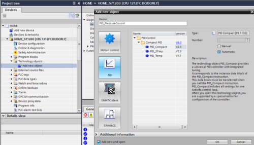
By selecting “Add new object” under the “Technology objects” folder, I select “PID” in the left pane and then “PID_Compact”:
I then gave the PID Object a name of “PID_PressureControl”:
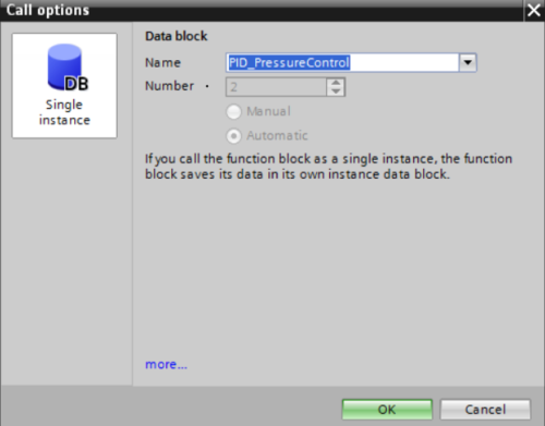
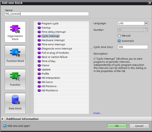
I added the PID Compact, at first, to a Network in my OB1 main block, but later I read that it should be in a cyclic interrupt organization block.
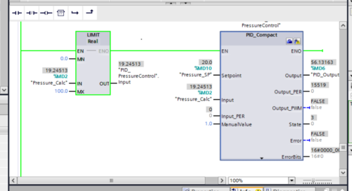
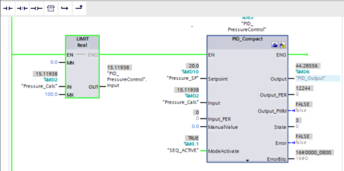
The Input is a memory tag called “Pressure_Calc” and the PID Output is a memory tag called “PID_Output”.
Note: As I don’t have any real-world analog signals to use, so I will create a sort of simulation to work with here, but if I were using real world analog signals I would use the “Input_PER” and Output_PER” parameters instead of the “Input” and “Output” parameters.
Here I later built an organization block (cyclic interrupt) at 300ms and moved my PID Controls into that block.
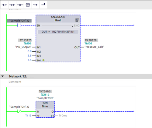
Normally, I would use some kind of LEAD_LAG instruction to capture the PID Output and “LAG” the output for some time and bring it back to the PID Input.
As far as I could tell, there is no LEAD_LAG block in the S7-1200 (though in documentation it appears the instruction is available in the S7 300 and 1500 models). For this, I used a timer with a calculation block and created a LEAD_LAG instruction to help me implement this PID for the time being.
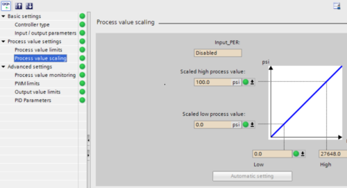
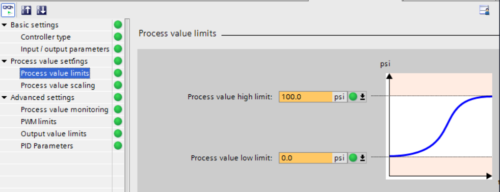
In the same fashion as other configuration properties, I went through the PID configuration parameters and set the low and high scaling and limits.
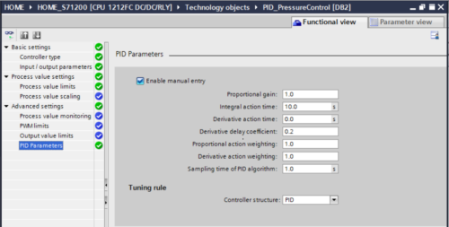
There is also a “PID Parameters” section where you can adjust the Gain, Integral etc.. by first checking the box that says “Enable manual entry”.
Mode Manipulation
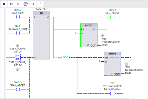
I also added logic to set the mode of my PID Loop to “3” (AUTO) when my sprinkler sequence is active and set the mode to “4” (MANUAL) when my sprinkler sequence is not active.
Here, I attached the “SEQ_ACTIVE” bit to the “ModeActivate” parameter. I set the “ManualValue” parameter to “0” as this is what the PID Output will resort to when placed in Manual Mode.
Commissioning
I will be honest, I did not get into the commissioning tool of the PID much, but the TIA Portal Software has a Commissioning Tool that will allow the system to tune a PID loop. Maybe I can come back to this in another article.
Adding the PID Indications to my HMI Project
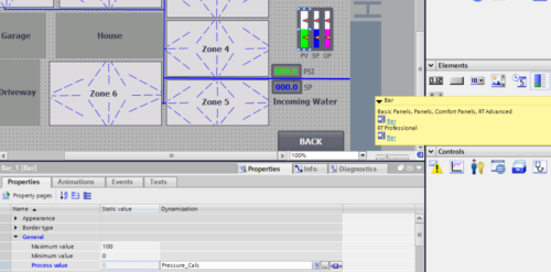
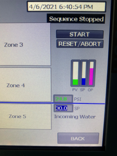
I also added the PID loop as an indicator to my HMI project and downloaded it to the Basic HMI Panel.
In the “Properties” tab of each “Bar” object, I selected the PLC tag associated, selected the colors I wished the bar to fill and made sure the scaling was correct.
References:
Conclusion
Again, a lot of steps but they are straightforward and relatively easy to implement.
I can’t stress enough the importance of reading and learning the parameters of any object or instruction that is to be used.
I still have plenty of learning to do with the “PID_Compact”, so I will keep at it until I am proficient in implementation.
Written by Brandon Cooper
Senior Controls Engineer and Freelance Writer
Have a question? Join our community of pros to take part in the discussion! You'll also find all of our automation courses at TheAutomationSchool.com.
Sponsor and Advertise: Get your product or service in front of our 75K followers while also supporting independent automation journalism by sponsoring or advertising with us! Learn more in our Media Guide here, or contact us using this form.
- Things I’ve Learned Travelling for Work (2) - July 17, 2025
- Things I’ve Learned Travelling for Work (1) - July 10, 2025
- Emulating an Allen-Bradley E3 or E3 Plus - June 30, 2025

Discover more from The Automation Blog
Subscribe to get the latest posts sent to your email.


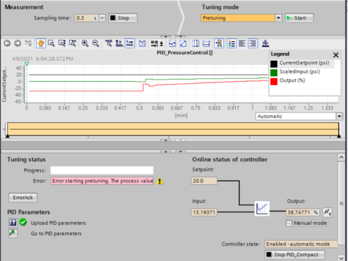


PID commissioning doesn’t work with a simulated value very well. Reason is because the calculator is expecting fluctuations on the pv when it flickers the cv.
Also when you tune you must get the cv and pv very close when you start. There is a sequence in the manual to follow the little text at the bottom of the pid viewer also can help but it will move through the steps very fast.
Good points!
Shawn
[sc name="stsigcom"]