The KTP700 Basic HMI includes a feature that also allows it to connect to PLC systems other than Siemens PLC’s. This could be of helpful to those looking for a single HMI model that connects to different control systems.
With that in mind, I did some research to see if I could setup my Siemens Basic Panel to connect to an Allen-Bradley ControlLogix over Ethernet, and in this article I’ll share how I made it work.
Adding EtherNet/IP Connection to Existing Program
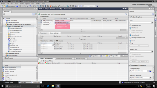
My first attempt was to open my existing application for my S7-1200, and under connections add Ethernet/IP to connect to a ControlLogix PLC.
But when I selected the “Allen-Bradley EtherNet I/P” Driver, I received this error: “This Combination of protocols is not permitted”.
I would assume this means that my Basic HMI will not connect to my S7 1200 via PROFINET and a ControlLogix via Ethernet/IP at the same time, so I’ll need to create a new HMI project to connect to only the ControlLogix PLC.

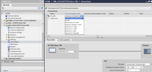
Next, I created a new Basic HMI Device called “HMI_Logix”
Connections setup:
-
Name:
I used my ControlLogix Processor Name “PC_LAB”
-
Communication Driver:
I selected “Allen-Bradley Ethernet/IP”
At the bottom right of the screenshot, you also see a “PLC” Configuration Area
-
I selected “ControlLogix, CompactLogix”
-
I added the “IP Address” of the Ethernet Module in my ControlLogix Chassis
-
I added the “Communication Path” from my Ethernet Module in the ControlLogix Chassis to the Processor which is 1,0 (1 = Backplane, 0 = Slot 0)
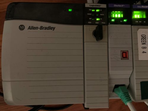
The ControlLogix Processor in question is a 5562 model running v19.11:
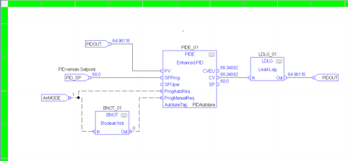
In the ControlLogix L62 I created an FBD routine with an Enhanced PID called “PIDE_01” which I’ll use for my Basic Panel HMI Project:
Adding HMI Tags in the TIA Portal Project
-
HMI tags:
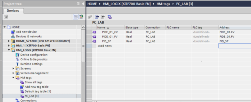
Here I selected “Add new tag table” and named it “PC_LAB” after my Logix Processor
Then I created three tags used in the enhanced PID Logic for PV, SP and CV.
Next I created an HMI Screen called “Logix_Data”.
I’m showing the three values as well as a Trend graphical object from the library with the three HMI tags trended in the display.
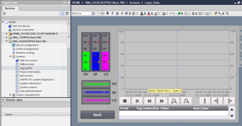 The trend was very easy to set up, I basically went into the “properties” window, changed a couple of background colors, added the trend tags and changed the pens for each trend tag to match the colors that I used on the bar indicators and numeric values on the display.
I then compiled and loaded my “HMI_Logix” program into the KTP700.
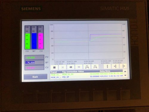
And once it was up and running I was able to make a setpoint change and watch the trend as the Enhanced PID reacted:
Conclusion
It was very easy setup to make the KTP700 communicate with a ControlLogix Processor.
It could be a drawback for someone that needs the HMI to communicate with a ControlLogix PLC and a Siemens PLC at the same time, but if you are only communicating with one or the other, then it is certainly a viable option as engineering time is very low with this HMI.
TIA Portal makes configuration as straight forward as it should be and I am really enjoying working with it
Written by Brandon Cooper
Senior Controls Engineer and Freelance Writer
Have a question? Join our community of pros to take part in the discussion! You'll also find all of our automation courses at TheAutomationSchool.com.
Sponsor and Advertise: Get your product or service in front of our 75K followers while also supporting independent automation journalism by sponsoring or advertising with us! Learn more in our Media Guide here, or contact us using this form.
- Things I’ve Learned Travelling for Work (2) - July 17, 2025
- Things I’ve Learned Travelling for Work (1) - July 10, 2025
- Emulating an Allen-Bradley E3 or E3 Plus - June 30, 2025

Discover more from The Automation Blog
Subscribe to get the latest posts sent to your email.


