
In Today’s article I walk you through how to Message data over Ethernet using the MSG instruction from a MicroLogix 1400 to a SLC-5/05 .
Note: In this example I have a MicroLogix 1400 at IP Address 192.168.1.66, and a SLC-5/05 at IP Address 192.168.1.47. Both have the same subnet address, and are attached to the same network via an Ethernet switch. Each program also had the N7 file expanded to 10 words, and the MicroLogix program has a free running Timer in Rung 0 of Program File 2 as seen below:
 Step 1) My first step is to add a new Rung to Program File 2 of my MicroLogix 1400 program. Then I add a MSG instruction to that rung:
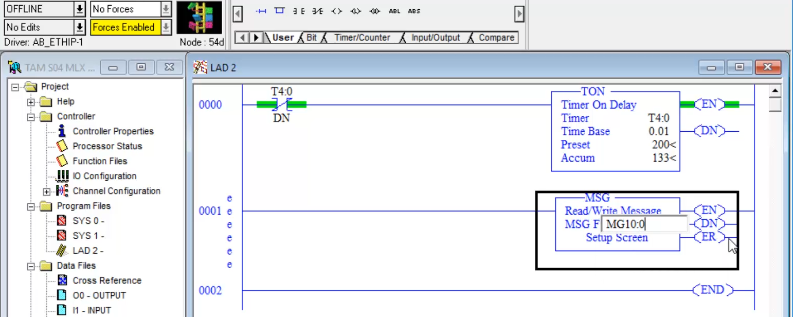
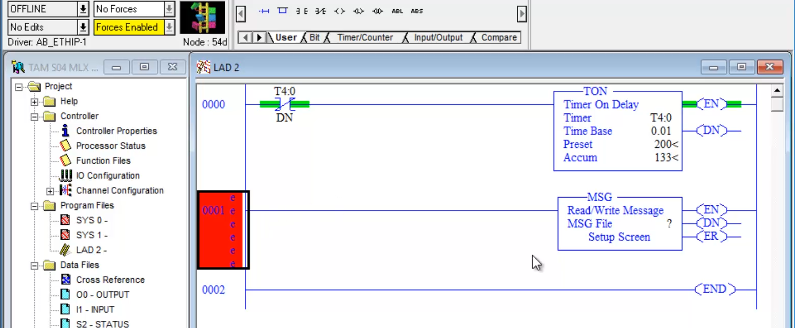 Step 2) Next, I assign a MSG File to the MSG Instruction. In this example I chose MG10:0:
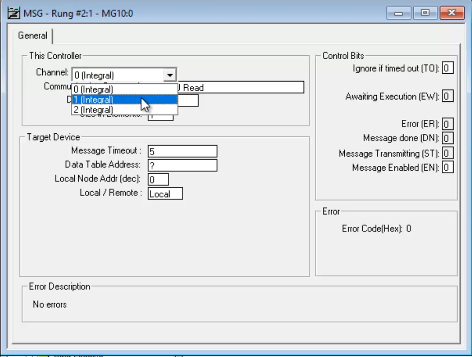
 Step 3) Now in the MSG Setup Screen I set the Channel the MSG instruction will use to 1 since that is the Ethernet channel on the MicroLogix 1400:
 Step 4) And since I’m writing data from this MicroLogix 1400 to a SLC-5/05, I change the Communication Command to 500CPU Write:
 Step 5) Next I need to set the Data Table Address in the MicroLogix 1400 that I’ll be messaging to my target SLC-5/05 controller. In this example I chose N7:0:
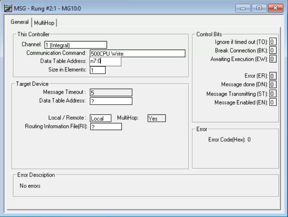
Step 6) Next I need to set how many “Elements” I’d like to send, starting from the previously chosen Data Table Address. In this example I chose a size of just 1 word.
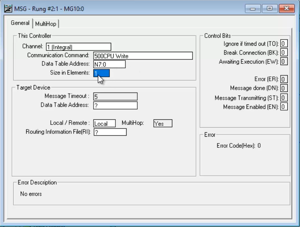
Step 7) Now under Target Device I set the Data Table Address I want to write the data to in the target PLC, which in this example is also N7:0:
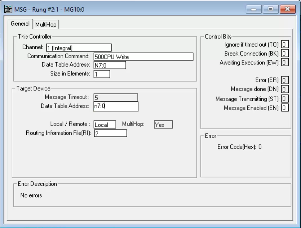 Note: The Target Device’s Data Table Address does not have to be the same address as the Source Address.
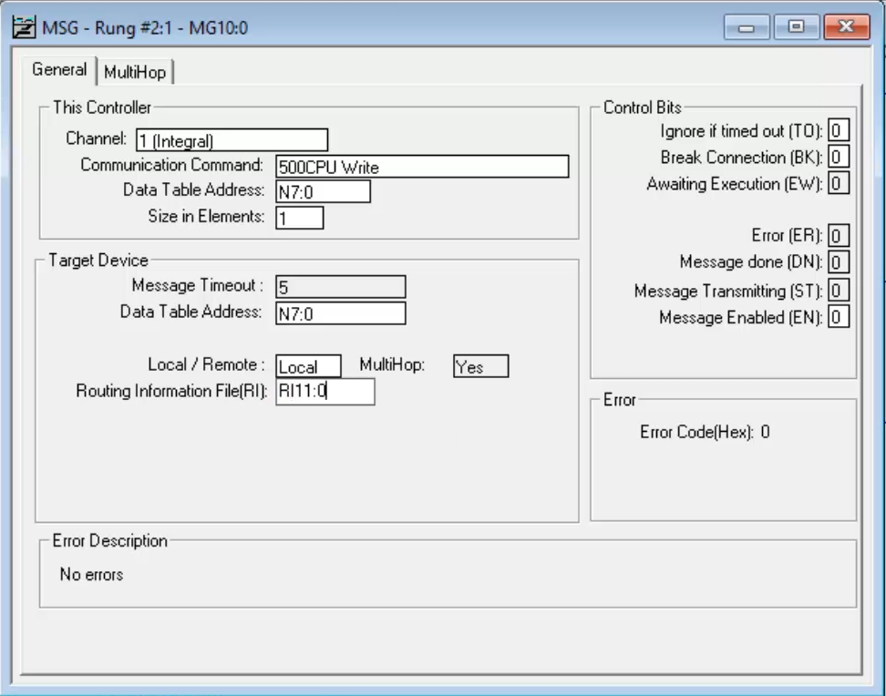
Step 8) The final setting I need to fill in on this tab that is the Routing Information File, which for this example I use file RI11:0:
Step 9) Now I navigate to the MultiHop tab:
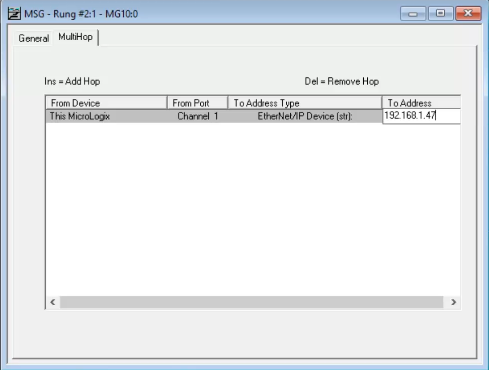
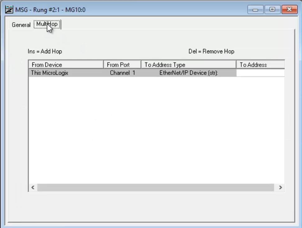 Step 10) Where I fill in the IP address of the target SLC-5/05 in the To Address field. Then I close the Message Setup Screen:
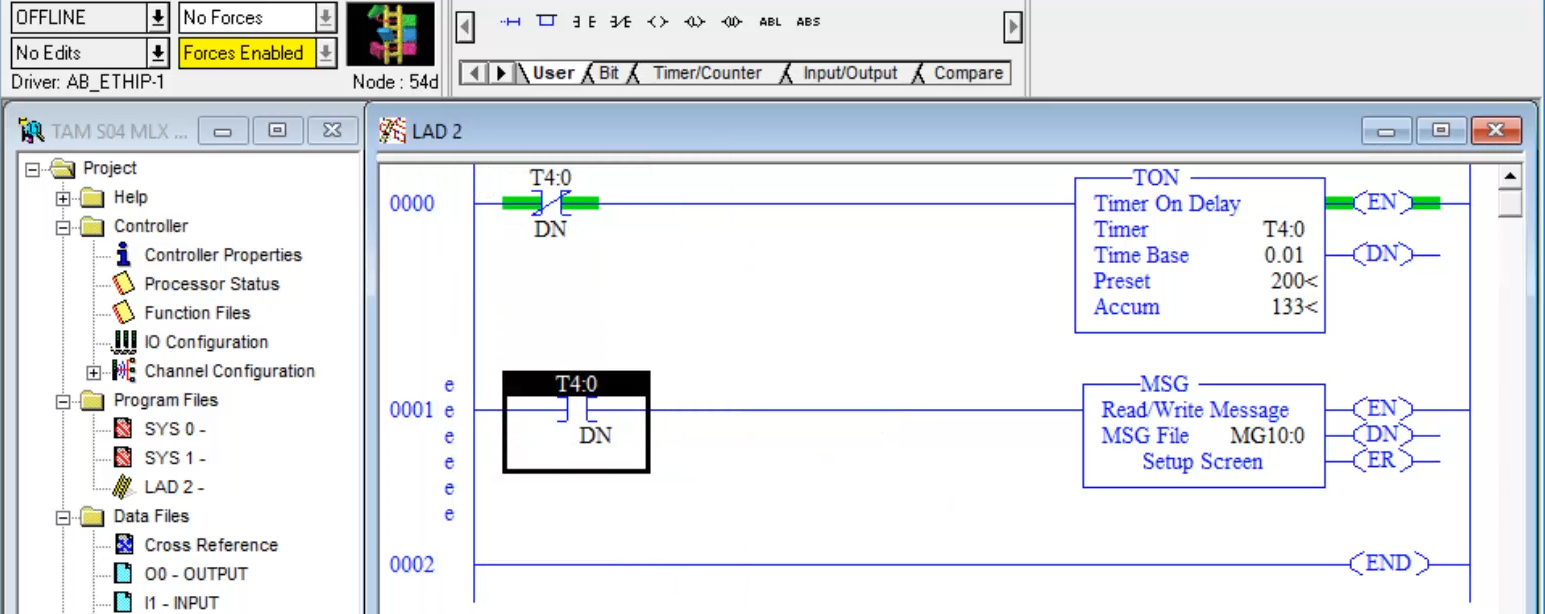
 Step 11) Back in Ladder File 2, I place an XIC in front of the MSG instruction. For the XIC instruction’s address I use the Done Bit of my existing two second free running Timer. This will trigger the message every two seconds, a slow enough period that I’d be able to see the resulting status of each message attempt before the next message attempt is made:
 Note: Since A-B Programmable Controllers have limited buffer space for MSG instructions, it’s typically not recommended to have multiple unconditional MSG instructions in your program. Instead, consider interlocking messages or triggering them based on timers, to insure you never overfill your controller’s message buffer. Doing so can also eliminate unwanted network traffic that unconditional / continuous Messages can generate.
Step 12) With my program now complete, I download it to my MicroLogix 1400 and run it.
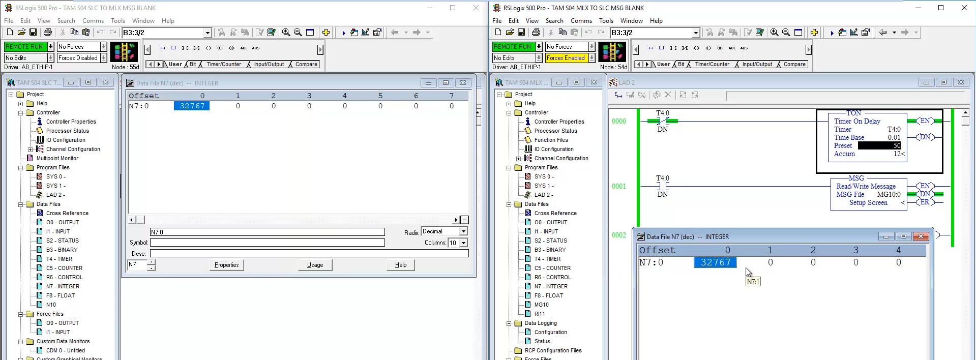
Step 13) Now any value I enter into N7:0 in the MicroLogix 1400 is message to, and shows up in N7:0 in the SLC-5/05 after a short delay:
To watch a video demonstration of the above, check out Episode 43 of The Automation Minute Season 4 below:
If you found this article helpful, please share it with your colleagues on LinkedIn, Facebook, Twitter or Goggle Plus!
And if you know anyone who would benefit from Allen-Bradley PLC, HMI, or SCADA training, please let them know about my affordable courses over at TheAutomation School.
You can also share your own thoughts and opinions on this subject by clicking on the “post a comment or question” link below.
Until next time, Peace ✌️
If you enjoyed this content, please give it a Like, and consider Sharing a link to it as that is the best way for us to grow our audience, which in turn allows us to produce more content 🙂
Shawn M Tierney
Technology Enthusiast & Content Creator
Support our work and gain access to hundreds members only articles and videos by becoming a member at The Automation Blog or on YouTube. You’ll also find all of my affordable PLC, HMI, and SCADA courses at TheAutomationSchool.com.
- Digital Twin Discussion with Arthur Alter of Smart Spatial (01/15/26) - January 15, 2026
- PRONETIQS: Measure, Monitor, and Maintain (P257) - January 14, 2026
- FactoryTalk Design Workbench First Look, CCW Comparison - December 19, 2025

Discover more from The Automation Blog
Subscribe to get the latest posts sent to your email.




Excelente
Thanks a lot
You’re welcome – check out the rest of my 100+ MicroLogix articles/videos here:
– https://theautomationblog.com/micrologix-guide/
Shawn