Let’s talk about something that is not only a large portion of any controls engineer’s duties but is one of the most important aspects of my career…specifying the components for your automation project. In the order of joy in my work, this is second-place only to the fun of bringing it all to life with some code and a little power.
The power-up and commissioning is, of course, my favorite part and can be very rewarding if the design is done correctly upfront. With that said, this will be a two-part overview of what steps I take on a general design as I get started so that the commissioning goes as smoothly as possible.
These steps, of course, can vary depending on the scope as well as the engineer’s approach. This is meant to only give a basic idea of an approach that has worked for me for 25 years.
Here is a quick list of what I would consider my main steps.
- Concept (Scope) – Part One
- General components – Part One
- Panel size – Part One
- Layout – Part One
- Design Detail/Schematics Generation – Part Two
- Connectivity and Additional components added – Part Two
- BOM – Part Two
Concept:
This is where the general operation of the machine or system and scope of the project is evaluated. After the scope is established, typically I will take any similar designs (from projects that are recently done or some that are recent enough to still be remembered by myself or teammates) into consideration as a template or as a good starting point before proceeding. This has the potential to greatly reduce any “cradle to grave” time for the design and commissioning. If all the differences between the new project and template are simple, like some sizing of motors, you can quickly update a few overload protection components and BOM line items to get the project kicked off in the right direction.
General Components:
I consider the general components to be the enclosure(s) (used to set back panel sizing), PLC and HMI selection, and any other major panel components such as drives, contactors, servos, transformers (if mounted on the back panel or enclosure), estimated fusing holder count (finalized amperage sizing and count in Design Detail), and any relays (simple safety, programmable safety, and terminal or ice-cube relays).

Panel Size:
Here is where having an example or a template helps cut the most time. This is the step where I want to work closely with the mechanical designer or system designer so I can be sure to know if there is more clearance or restricted dimensions in either the vertical or horizontal direction. This will give me an initial idea of the orientation of the cabinet.

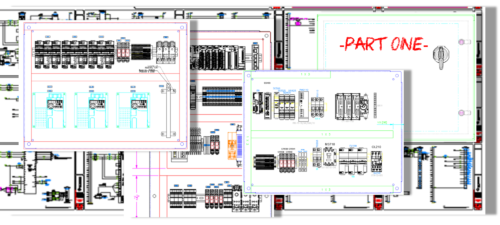
I will also want to know what clearances there are around the enclosure to narrow down to a single or multiple-door enclosure. Otherwise, in the cad package (I have always used AutoCAD) I just start putting the one-to-one scaled drawings of the components side-by-side and in an arrangement that also ensures separation of the higher voltage (240 Vac or 480 Vac) items and the control voltage (typically 24 Vdc these days).
Once roughed in, I may draw a rectangle around the parts and measure with some dimensions to get a rough idea so I can narrow it down to the size of the back panel. I will typically grab a commonly used or standard back panel drawing and use it instead of the rectangle approach.
Don’t forget the importance of any needed space for wire trough or cable management. Another important detail here is the clearances you need to consider around any drives, disconnects, or other higher wattage loss items that may generate heat.
Once you get here, you can narrow it down to a standard size from your preferred vendor or stocked items. I do find that, although rare, a custom enclosure may be the best option.
Panel Layout:
The keys to a successful panel layout are accurate 1:1 drawings of the panel, components, and being sure you have the right dimensions for any wire trough you use. From day one in my career, I learned that a component drawing used on the panel that did not include the same dimensions as the purchased part, meant a real headache for the assembly personnel as they tried to get everything to fit.
Possibly even the purchase of a new panel to accommodate the difference. At this OEM, a specific wire trough used had always been drawn to size. This did not include the dimensions of the wire tray cover. This small amount built up to quite a distance when used over a larger panel.
I will also use the dimensions for the location of the disconnect location first and lay the other components around that fixed position. This step is important to remember the location of the through-the-door operation handle. Getting those dimensions relative to the location of the panel should most likely be the first step in the panel layout.
I hope you found this first part of my two part series helpful! In the next part I’ll get into the finer details of the Schematic Design and BOM.
Written by Paul Hunt
Senior Automation Engineer and Freelance Writer
Have a question? Join our community of pros to take part in the discussion! You'll also find all of our automation courses at TheAutomationSchool.com.
Sponsor and Advertise: Get your product or service in front of our 75K followers while also supporting independent automation journalism by sponsoring or advertising with us! Learn more in our Media Guide here, or contact us using this form.
- Mitsubishi PLCs: Brief History and Hardware Overview - August 2, 2022
- Mitsubishi PLCs: FX5 vs iQ-R - February 10, 2022
- How To Register and Use a Device Profile in GX Works3 - November 9, 2021

Discover more from The Automation Blog
Subscribe to get the latest posts sent to your email.


