
I believe that in the world of control systems, the little things can make a huge impact.
The little things we do ahead of problems will determine how well we diagnose and repair issues when they arise. It can mean the difference in troubleshooting time in seconds instead of hours.
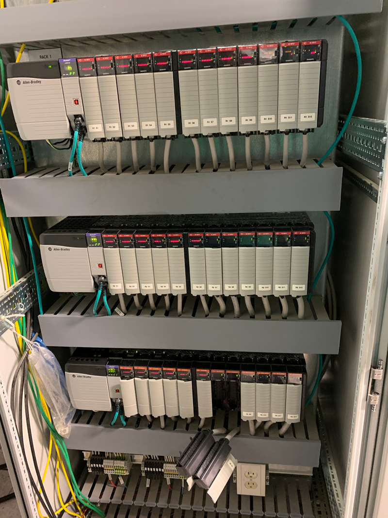
Image by: Brandon Cooper
Sometimes, the little things are available, but not utilized. Especially in a PLC system, the functions are available, but they must be implemented.
For instance, if you are using diagnostic I/O modules in a ControlLogix system, there are parameters available for monitoring and interacting with the modules, but many times, these parameters go without utilization.
Maybe today is the day to change that. Maybe today, we change the details of our systems to aid the troubleshooter to diagnose and repair failure as efficiently as possible.
Diagnostic Information
So, what information is available? Let’s take-a-look at for instance a 1756-OA8D module. There are several monitoring parameters available:
FUSE BLOWN:
This parameter will indicate that an electronic fuse inside the module has tripped. This is not a real fuse. It can be reset inside the module properties in Studio 5000 or we will later see, in this article, that it can be reset in logic.
NO LOAD:
This parameter detects no leakage current through the output load, most likely indicating a broken circuit
NO OUTPUT VERIFICATION:
This parameter means that the Output Module was unable to detect any change of state at the output circuitry even though a change from “OFF” to “ON” was ordered.
NO FIELD POWER:
This parameter detects that no 120 VAC Power is present on the incoming side of the module relay. Look at drawings to determine where external power comes from.
The following indications would be the parameters that could be monitored or alarmed for one channel of one I/O Module. What can be done with this is simply a limit of the imagination.
Image by: Brandon Cooper
Using the PLC Program to Interact with the Module
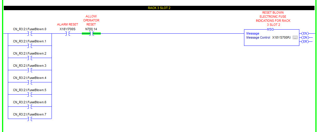
I mentioned above that the module’s electronic fuse can be reset using ladder logic and we will take-a-look here at how that can be accomplished. In the screenshot below, if a fuse is blown, an external reset button could trigger an MSG instruction to write to the I/O Module.
Image by: Brandon Cooper
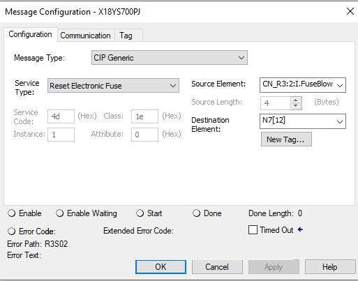
Inside the MSG instruction, the tabs will be set up as follows:
Image by: Brandon Cooper
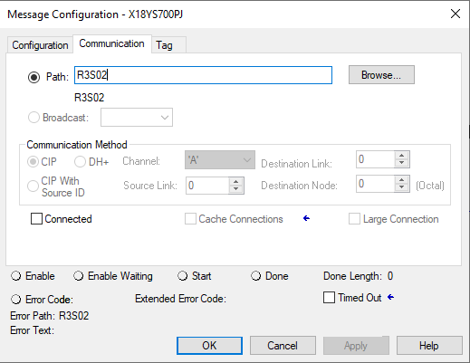
The communication path is the path to the I/O Module in the Studio 5000 I/O Configuration Tree:
Image by: Brandon Cooper
Conclusion
One of my main personal drivers is to make something better every day. What we do with the little things can make someone else’s life easier as well as mitigate or reduce downtime and that is what it is all about.
If I, as a control system engineer, can make just one improvement a day, think about what a year can bring.
Written by Brandon Cooper
Senior Controls Engineer and Freelance Writer
Have a question? Join our community of pros to take part in the discussion! You'll also find all of our automation courses at TheAutomationSchool.com.
Sponsor and Advertise: Get your product or service in front of our 75K followers while also supporting independent automation journalism by sponsoring or advertising with us! Learn more in our Media Guide here, or contact us using this form.
- Things I’ve Learned Travelling for Work (2) - July 17, 2025
- Things I’ve Learned Travelling for Work (1) - July 10, 2025
- Emulating an Allen-Bradley E3 or E3 Plus - June 30, 2025

Discover more from The Automation Blog
Subscribe to get the latest posts sent to your email.





Situation:
I am trying to get the PLC to recognize when an HMI restarts. I noticed that the GSV command in the PLC might be able to get me this information using the Module class name. From here I would be able to use “equal to” commands along with output energizers (to test if it is working before I utilize it the way I want to). I would set the the Module equal to the value “16#5000” which would energize the output when the HMI is shutting down for the restart.
Question:
The problem is that the HMI is not in the I/O tree already. If I were to add this to the tree, would I have to shut the machine down or is there a way to add the HMI to the tree without shutting the machine down?
I’m curious which PLC and HMI you are using, specifically?
I could guest it’s a ControlLogix L73 v30 and PV5510 v5, but you could be using one of a hundred different combinations.
Shawn
[sc name="stsigcom"]
I am using a Panelview Plus 1500 HMI, but I am not 100% sure which PLC (I am an Intern). I believe it is a CompactLogix5343 if that sounds right?
PVPlus doesn’t get added to the IO Tree like the PV5000, and I don’t think the old 43 supports the PV5000 series.
To avoid going in circles, your next steps should be to get the exact catalog numbers and firmware versions off each device. Note that the firmware installed on these devices is most likely not what’s on the label.
Good luck!
Shawn
[sc name="stsigcom"]