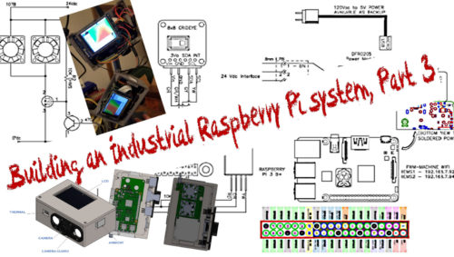
Up to this point I have a complete system… almost. The enclosure (still with a few revisions to go) is essentially complete, and everything has been mounted and fits.
However, the system still needs code to function. So now I dive in headfirst with a system I have never used before and code I do not know.
Links to previous parts of this series:
I spent quite a bit of time searching the web for various help topics and forum posts to help with various aspects of troubleshooting as I got on with the setup and power up. This is definitely a good use of the web as a tool for research and support.
Turns out that I am NOT the first noob to try and set up a Raspberry Pi with an LCD or any of the other components. There are also plenty of experienced users that are willing to help in forums or even by email.
I started with the Raspberry Pi and the PiTFT from Adafruit. There were plenty of helpful tips out there that can get anyone to the point that it will power up and display the same as the Pi does by default out the HDMI port when first powered up.
This may take some trial and error with the editing of a couple config files, but not something too difficult to do with some careful following of a web tutorial or two.
The functioning LCD got me excited since the touch and both the display options were all nice additions, essential in my opinion, to this system.
If I could do it again, I would go with one a larger screen (LCD used is only a 2.8”). Other larger options looked to interface the same.
I feel that the use of references and tutorials is a crucial aspect of any project you undertake like this. The less familiar you are with components or the combination of, the more imperative it is to have resources (web searching, journals, or specific websites) that you can refer to for ideas to help with what you want to achieve.
Using the standard Python editor (Thonny) that came included on the OS worked perfectly for me. The only thing to keep an eye on when doing this is the version of Python being used.
I did have to be sure I was editing and running on a specific version that worked with all the code examples I was using.
One instance was with the Scipy code being used for the thermal sensor. I ran into an issue when compiling with a fault for the module not being found.
I then ran a command line using a direct reference to the Python version (3) I found on a forum:
sudo apt-get install -y python3-scipy python3-pygame
That seemed to not only go through a complete install but also ran some additional items. It then worked perfectly!
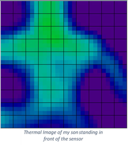
To save this image as a file that could be viewed later, I had to do a screenshot. This was done easily by using a specific Raspberry Pi API.
Declaration:
#use pyautogui for screenshot
import pyautogui #added for screenshot function
Use in script:
screenshot = pyautogui.screenshot()
screenshot.save(“screen.png”)
Now with the thermal sensor working, I can come back to the full implementation later. For now, it was time to move on to the function of the camera.
Since the Pi is set up and all ready to take a camera so easily, this was not too difficult. But for a noob, it was just a matter of following the code and setting things in the code that may be needed for the specific application.
For my application this involved some research onto some of the built-in parameters like rotate, setting the size of the image, and naming of the output file.
At the start of the code, I used the following to initiate the use of the camera…
import picamera
camera = picamera.PiCamera()
# ROTATE
#camera.vflip = True #can do horizontal flip too
camera.rotation=90
This line then is used in the code to do the capture, size it, and set the name for the output file.
camera.capture(‘image.jpg’, resize=(320, 240))
With the two imaging components functional, time to get started on the ambient sensor. This took a little more than the other sensors to implement.
I had to select a specific input point on the Pi as well as soldering a resistor into the circuit. On top of that, in the end, I had to use another 5 Vdc source for the sensor instead of an open and unused 3 Vdc.
The implementation of the sensor still had issues. I got data back from the sensor easily enough but found that it was not 100% consistent.
Also, the background process was causing issues when the script was run, stopped, and started again.
The fix for this took some time and lots of web crawling to figure out. The consistency issue had a work-around as well in the form of error trapping in the code.
In this project, I chose to simply write a line of text out to a log file that also monitored communications errors and timestamps of power cycling.
To get around the issue with the background process (libgpiod_pulsein), at each power-up I programmed a check to see if it was running. If it was, I killed it so the DHT sensor could then initiate properly.
I tried one suggested approach of killing the process using the process ID. This was not working as the ID was different in every instance.
I then chose to use the libgpiod_pulsein by name. This was easy to monitor using the “lxtask” from the command prompt. This pops up an app similar to Windows Task Manager.
########## DHT22 Sensor Process Kill if active ###################
def check_kill_process(pstring):
for line in os.popen(“ps ax | grep ” + pstring + ” | grep -v grep”):
fields = line.split()
pid = fields[0]
os.kill(int(pid), signal.SIGKILL)
check_kill_process(‘libgpiod_pulsein’)
# Initial the dht device, with data pin connected to:
dhtDevice = adafruit_dht.DHT22(board.D4)
##################################################
Sample of captured data from DHT22 Sensor:
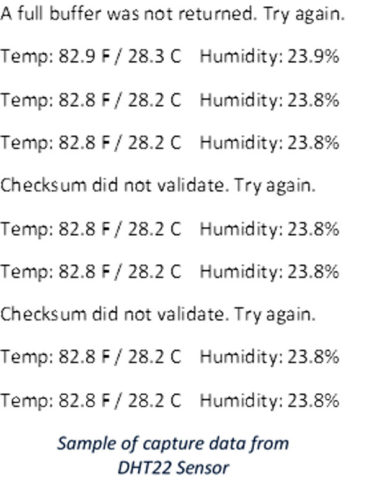 Now I was able to get values from the sensor and not shut down, restart, or fault out if issues arose with the connection. Time to move on.
One other issue the system had that was important to correct was the seemingly unstable and continuously dropping Wi-Fi.
There are a few things I found to try on the web that include setting the country code in the OS settings. This seemed to help at first.
The main stable fix came when I replaced the 24 Vdc to 5 Vdc regulator. The output when the input was 24 Vdc was only 4.6 Vdc.
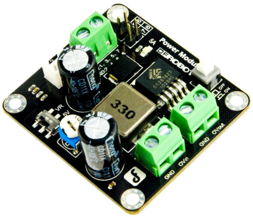
This was affecting performance as well as posting a warning on the display for low voltage. This was fixed with a variable buck-boost power supply.
This component was twice the size as the original regulator but luckily it fit. The power supply was purchased from DFRobot and allowed for 3.3-28 Vdc in with 3-24 Vdc out at 25 Watts.
At 5 (or 5.1) Vdc out, this gave me plenty of current supply (5A) for the needed 3A the system required. When using one of these power supplies, be sure to check the output voltage first… I found out the hard way that the output was set to the max (24 Vdc) by default.
The Pi DID NOT like this.
One more item I tried with the Wi-Fi that the 3B+ Pi did not like was a USB Wi-Fi antenna.
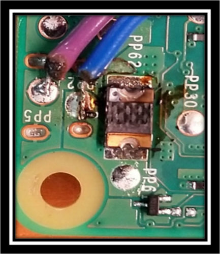
This was apparently too much for the Pi to supply with the already connected LCD, camera, thermal sensor, and ambient sensor. It seems that the internal power supply bit the dust on that one.
Come back for Part IV (the final one) that will discuss the various script files and implementation.
Written by Paul Hunt
Senior Automation Engineer and Freelance Writer
Have a question? Join our community of pros to take part in the discussion! You'll also find all of our automation courses at TheAutomationSchool.com.
Sponsor and Advertise: Get your product or service in front of our 75K followers while also supporting independent automation journalism by sponsoring or advertising with us! Learn more in our Media Guide here, or contact us using this form.
- Mitsubishi PLCs: Brief History and Hardware Overview - August 2, 2022
- Mitsubishi PLCs: FX5 vs iQ-R - February 10, 2022
- How To Register and Use a Device Profile in GX Works3 - November 9, 2021

Discover more from The Automation Blog
Subscribe to get the latest posts sent to your email.


