In this second part of my two part series, I want to talk about the largest portion of any controls engineer’s duties… specifying the components for your automation project.
As mentioned in part one, the power-up and commissioning is my favorite part (I am sure that I am not alone) and can be very rewarding if the proper amount of thought into the design is done upfront.
This is the continuation of the simple overview of what steps I take on a general design as I get started. These steps, of course, can vary depending on the scope as well as the engineer’s approach.
Here is the list again of what I would consider my main steps.
- Concept (Scope) – Part One
- General components – Part One
- Panel size – Part One
- Layout – Part One
- Design Detail/Schematics Generation – Part Two
- Connectivity and Additional components added – Part Two
- BOM – Part Two
Design Detail and Schematics:
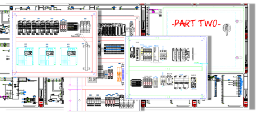
In this step, I take what I have laid out with the roughed-in panel drawings and get started with more detail. More detail in the panel component and location in relation to items that work best when closer together.

The most detail will most likely be in the wiring schematics needed for main power and controls power to bring life to the components on the back panel. This step could (and should) take the longest in the design portion of a project. A lot of time is spent reviewing and reading user manuals for any power requirements, fusing needs, connection requirements, minimum wiring sizes, heat dissipation, etc.
In the Cad drawing(s), depending on the abilities of the assembly personnel and your design department processes or standards, it is important to include wire gauge sizing. This could be just as important (or more) than dimensions on the panel layout. NFPA and any other codes that are pertinent (i.e., IEC and UL) should be kept close as the design progresses.

It is nice habit to get in to have any additional notes on drawings. These could include dip switch settings, parameters, cable numbers, and any motor sizing or part number information. This is very helpful not only for assembly verification but also for reviewing or using these prints for similar jobs in the future.
Additional Components:
As the detail and design phase progresses, there may be previously unknown additional items needed in conjunction with parts in the design or even system/machine design change requests.

These may be anything from items needed to actuate or activate specific controls, limiting functionality, more complexity such as robotics or additional automated system, or unforeseen safety items. Allow yourself room, time, and schematic space to add a page or two for unknowns.
This is easier to do when a set schematic standard or format is used for controls systems designs (i.e., a page for safety relay or power supply page). Keep in mind the needed panel spacing requirements for any additional components.
You want to be sure that space is not too compact, there is enough free air flow available, and it is not too challenging for not only the assembly personnel but for future access by any maintenance or support personnel that need to access items for preventive work and repair.
BOM:
Here it is, the last and final object of the design. The last chance to check your work before submitting purchase requests or being released to the floor for assembly.
I feel that it is best to use the bill of material to double-check your drawings. Sometimes an engineer is hard-pressed to take the precious time to do this step. Even so, it is very important. Go page by page and review the panel and/or enclosure layouts comparing the BOM as you go. I typically use a highlighter for this step.
I will go one line at a time and highlight the schematic drawing of a component while also highlighting the BOM line. This way you can be sure that all the items on the drawing are located on the BOM and vice-versa. It is a good way to be sure any details haven’t been missed.
One other key thing to remember on the BOM…update it even as the project build progresses. You don’t want to order another system in the future and forget that one little item. This will cause frustration and possibly lengthy delays in the build or commissioning.
Written by Paul Hunt
Senior Automation Engineer and Freelance Writer
Have a question? Join our community of pros to take part in the discussion! You'll also find all of our automation courses at TheAutomationSchool.com.
Sponsor and Advertise: Get your product or service in front of our 75K followers while also supporting independent automation journalism by sponsoring or advertising with us! Learn more in our Media Guide here, or contact us using this form.
- Mitsubishi PLCs: Brief History and Hardware Overview - August 2, 2022
- Mitsubishi PLCs: FX5 vs iQ-R - February 10, 2022
- How To Register and Use a Device Profile in GX Works3 - November 9, 2021

Discover more from The Automation Blog
Subscribe to get the latest posts sent to your email.


