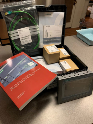
Now that I have my KTP700 Basic HMI included in my TIA Portal Project, it is time to create a couple of graphical displays that will allow me to interact with the program that I have running in the S7-1200 CPU.
I will begin using very basic static shapes and then add dynamic attributes to them, including visibility options based on when a sprinkler/zone is running, color change during certain conditions etc.
If you are familiar with Microsoft Windows, then you are familiar with building an HMI display in TIA Portal.
What I mean by that is, literally, if you need to find an attribute within an object, simply right-click and select “properties” and all of the attributes within that object will be displayed in the lower middle window of TIA Portal.
Creating a Graphic Display
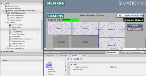
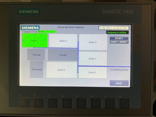
By selecting “Add new screen”, I created a graphic display called “LAWN” where I displayed the six sprinkler zones around my project home.
In the screenshot below, you can see that I have the “START” button selected and the “properties” window is displayed at the bottom of the TIA Portal window.
In this window, I can modify all the attributes associated with that “START” button. Here, I am setting a memory bit called “SEQ_Start” to a value of “1” in the HOME_S71200 CPU when I press the button and setting the same bit to “0” when I release the button.
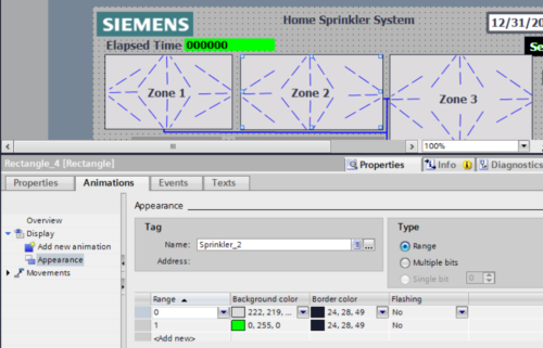
In this next screenshot, I am modifying the properties of the “Zone 2” rectangle to display as “Grey” when the “Sprinkler_2” output is “0” and “Green” when the “Sprinkler_2” output is “1”.
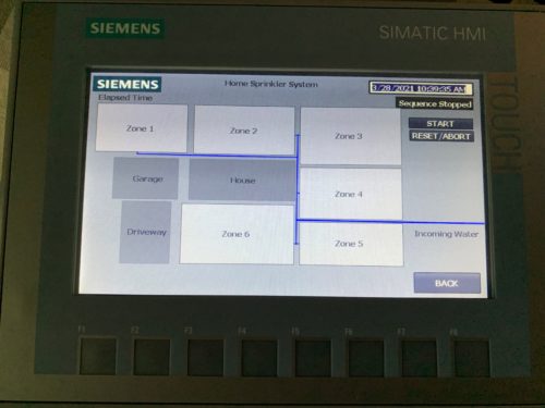
When I load the project and look at my “LAWN” display, it displays that the sprinkler sequence is “Stopped”.
I chose to use neutral “grey” colors. Color scheme design and thought in HMI displays is a book in itself, but whatever works for you and your company is what matters.
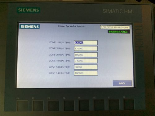
Here, I also built a graphic display called “LAWN_SETTINGS” where the values for how long the timer for each zone can be adjusted. This is the “ZONE_PRESETS[]” array in the HOME_S71200 CPU.
I now click the “START” button on the “LAWN” display and the sprinkler sequence becomes active. Zone 1 illuminates as it runs and the elapsed time for that zone appears.
I also test that the “RESET/ABORT” button functions as well as the page navigation buttons and Zone Preset Timers on the “LAWN_Settings” display. I now have a connected, functioning HMI for my sprinkler system.
Conclusion
The Simatic KTP700 Basic HMI has been very easy to “get to know”. It has taken very little research to add it to my project, connect it to the HOME_S71200 CPU and build a couple of graphic displays to interact with my program.
In the future, I hope to make enhancements to the system, explore more of the options and capabilities that the PLC and HMI have, and have them work together so I can learn more myself, as well as, share with others here on theautomationblog.com.
Written by Brandon Cooper
Senior Controls Engineer and Freelance Writer
Have a question? Join our community of pros to take part in the discussion! You'll also find all of our automation courses at TheAutomationSchool.com.
Sponsor and Advertise: Get your product or service in front of our 75K followers while also supporting independent automation journalism by sponsoring or advertising with us! Learn more in our Media Guide here, or contact us using this form.
- Things I’ve Learned Travelling for Work (2) - July 17, 2025
- Things I’ve Learned Travelling for Work (1) - July 10, 2025
- Emulating an Allen-Bradley E3 or E3 Plus - June 30, 2025

Discover more from The Automation Blog
Subscribe to get the latest posts sent to your email.


